
Automatic flow resistance control system for minimum flow

A control system and flow technology, applied in the field of flow resistance performance test system, can solve problems such as poor measurement continuity and difficult realization of precision requirements, and achieve the effects of increasing adjustment precision, low cost and simple principle

Active Publication Date: 2021-08-27
10TH RES INST OF CETC
View PDF13 Cites 4 Cited by
  • Summary
  • Abstract
  • Description
  • Claims
  • Application Information

AI Technical Summary

Problems solved by technology

[0011] The purpose of the present invention is to provide a real-time continuous measurement of small flow rate, which can improve the accuracy of flow resistance test and measure High-precision, simple and cheap small flow automatic measuring device, realizes the measurement of the flow resistance of the automatic test object under the extremely small flow, the automatic test of the flow resistance, and overcomes the poor measurement continuity and accuracy requirements during the extremely small flow test. Difficulty and other issues

Method used


Image

  • Automatic flow resistance control system for minimum flow
  • Automatic flow resistance control system for minimum flow

Examples


Embodiment Construction

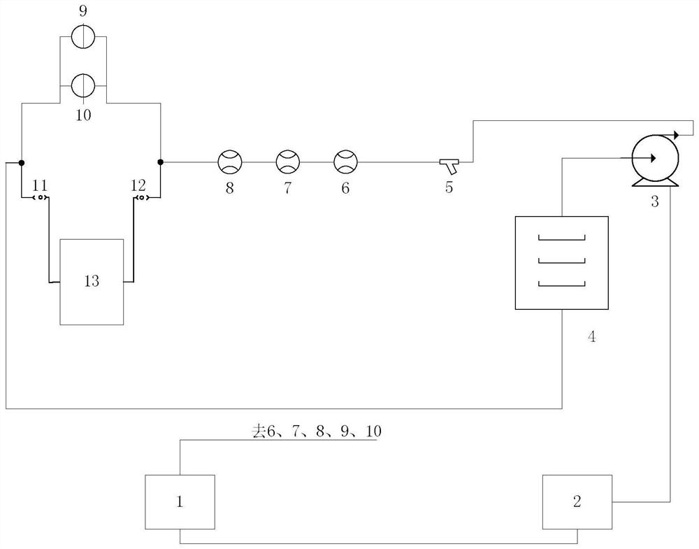
[0021] refer to figure 1 . In the preferred embodiment described below, a very small flow automatic flow resistance control system includes: a water tank 4 that provides circulating liquid to a positive displacement pump 3, a filter 5 and a positive displacement flowmeter 6 connected in series in the downstream direction , the differential pressure flowmeter 7 and the ultrasonic flowmeter 8 are connected to the differential pressure flowmeter of the cold plate 13 to be measured, wherein: the two ends of the cold plate 13 to be measured or the load (DUT) are connected in parallel with the first differential pressure sensor 9 The second differential pressure sensor 10 and the second quick self-sealing joint 12 communicate with the water tank 4 through the parallel closed-loop circuit formed by the first quick self-sealing joint 11, and communicate with the volumetric flow rate 6, the differential pressure flowmeter 7 and the ultrasonic flow rate through the positive displacement...


PUM


Abstract

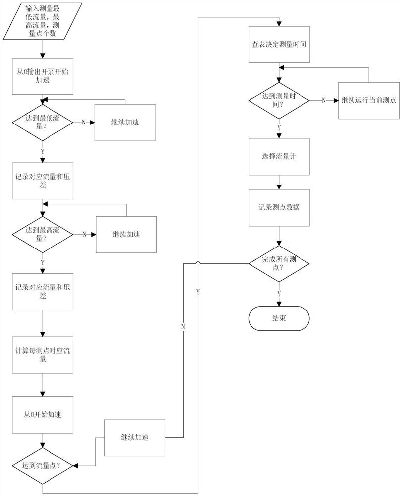
According to an automatic flow resistance control system for minimum flow, a small flow can be continuously measured in real time, and the measurement precision is high. According to the technical scheme, a positive displacement pump is communicated with a flow and flow resistance circulation loop formed by series flow pipes of a positive displacement flow meter, a differential pressure flow meter and an ultrasonic flow meter, and the flow and flow resistance circulation loop is connected with a PWM voltage converter through a single-chip microcomputer; and the single-chip microcomputer 1 realizes equal proportion conversion of a duty ratio PWM signal and a voltage signal through a PWM signal-to-analog signal module to form a direct current control voltage to drive a motor, the single-chip microcomputer selects a reading of a corresponding measuring range flow meter to directly drive a dual-mode PWM control circuit in a pump motor to adjust the rotating speed of the motor and a pump, the readings of the selected flow meter and the differential pressure sensor at the corresponding moment are collected at the tail of each time slice to form measuring points, then the measuring step length is automatically set according to the number of the input measuring points, and the measurement of the differential pressure and the flow in the measuring range is achieved.

Description

technical field [0001] The invention relates to a flow resistance performance test system for fluid mechanical products such as various cold water systems, radiators, and water cooling plates, especially an automatic flow resistance control system with a flow rate lower than 500mL / min. Background technique [0002] With the development of microelectronics technology, the electronic module cooling system has developed from cold plate conduction liquid cooling to module through cooling liquid cooling. On the other hand, different channel designs in modules lead to different hydraulic characteristics, which have a major impact on the actual liquid supply flow of a single module, making the flow of cooling liquid provided by a single module cooling smaller and smaller, and the power consumption of the chip is getting smaller and smaller. High, the more complex the strengthened surface inside the electronic module, the greater the flow resistance, and the smaller the actual flow ...

Claims


Application Information

Patent Timeline
Patent Type & Authority Applications(China)
IPC IPC(8): G01M10/00
CPCG01M10/00
Inventor 胡家渝
Owner 10TH RES INST OF CETC
Learn More