S-shaped bent waveguide with offset and groove

A curved waveguide and groove technology, applied in the field of low-loss S-shaped curved waveguide, to achieve the effect of low-loss optical waveguide interconnection unit design, reduced bending loss, and compact size

Pending Publication Date: 2021-08-27
GUILIN UNIV OF ELECTRONIC TECH
View PDF0 Cites 2 Cited by
  • Summary
  • Abstract
  • Description
  • Claims
  • Application Information

AI Technical Summary

Problems solved by technology

At present, how to reduce the bending loss of low-index-difference polymer S-bend waveguides has not been studied

Method used


Image

  • S-shaped bent waveguide with offset and groove
  • S-shaped bent waveguide with offset and groove
  • S-shaped bent waveguide with offset and groove

Examples


Embodiment Construction

[0023] The present invention will be further described in detail below through specific embodiments in conjunction with the accompanying drawings. The present application can be implemented in many different forms, and is not limited to the implementation manner described in this embodiment. The purpose of providing the following specific embodiments is to facilitate a clearer and more thorough understanding of the content of the present invention.

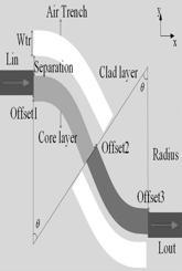
[0024] refer to Figure 1 to Figure 5 , the present invention proposes an S-shaped curved waveguide structure with offsets and grooves, such as figure 1 As shown, the input straight waveguide Lin of the S-shaped curved waveguide and the first curved waveguide segment Bend 1 The offset d is introduced at the connection 1 , the first curved waveguide segment Bend 1 with the second curved waveguide section Bend 2 The offset d is introduced at the connection 2 , the second curved waveguide section Bend 2 The offset d is introdu...


PUM

PropertyMeasurementUnit
radiusaaaaaaaaaa

Abstract

The invention provides an S-shaped bent waveguide structure with offset and grooves. The S-shaped bent waveguide structure comprises an input straight waveguide, two bent waveguides with opposite curvatures and the same radius, an output straight waveguide, offset at each waveguide joint and the grooves filled with low-refractive-index media. The S-shaped bent optical waveguide structure with the offset and the grooves is characterized in that certain offset is introduced into the connection part of the input straight waveguide and a first bent waveguide section, the connection part of bent waveguide sections with opposite curvatures and the same radius and the connection part of a second bent waveguide section and an output straight waveguide section in an S-shaped waveguide respectively; two grooves with the same shape are added to the outer sides of two bent arc sections respectively, the grooves are filled with air, waveguide core widths are consistent, and a small difference value exists between the refractive indexes of a waveguide core layer and a wrapping layer. The S-shaped waveguide with a small refractive index difference can generate obvious bending loss under a small bending radius, transition loss and radiation loss existing in the S-shaped bent waveguide can be correspondingly reduced by introducing the offset and grooves with proper sizes, and therefore the low-loss transmission of the S-shaped bending waveguide is achieved. According to the invention, compact-size and low-loss optical path design in optical interconnection can be realized.

Description

technical field [0001] The invention relates to an optical waveguide device, an optical interconnection unit and the technical field of optical communication, in particular to a low-loss S-shaped curved waveguide. Background technique [0002] Compared with traditional copper-based electrical interconnects, optical interconnects have excellent performance in terms of electromagnetic interference, bandwidth scalability, power consumption, and system density. The key bending waveguide components that form optical interconnections on complex boards include L bends, V Bending, U-bending and S-bending etc. Among them, the S-shaped curved waveguide plays a vital role in the connection and interconnection of modules or devices at different positions on the board or between chips. The materials used for the preparation of waveguide structures mainly include Si / SiO 2 , SiN / SiO 2 and polymers etc. The refractive index difference between the waveguide core and the cladding has a gr...

Claims


Application Information

Patent Timeline
Patent Type & Authority Applications(China)
IPC IPC(8): G02B6/125
CPCG02B6/125
Inventor 尚玉玲郭文杰何翔李春泉王佳奇赵雅敏周谨卓谢文强
Owner GUILIN UNIV OF ELECTRONIC TECH
Why Eureka
Try Eureka