

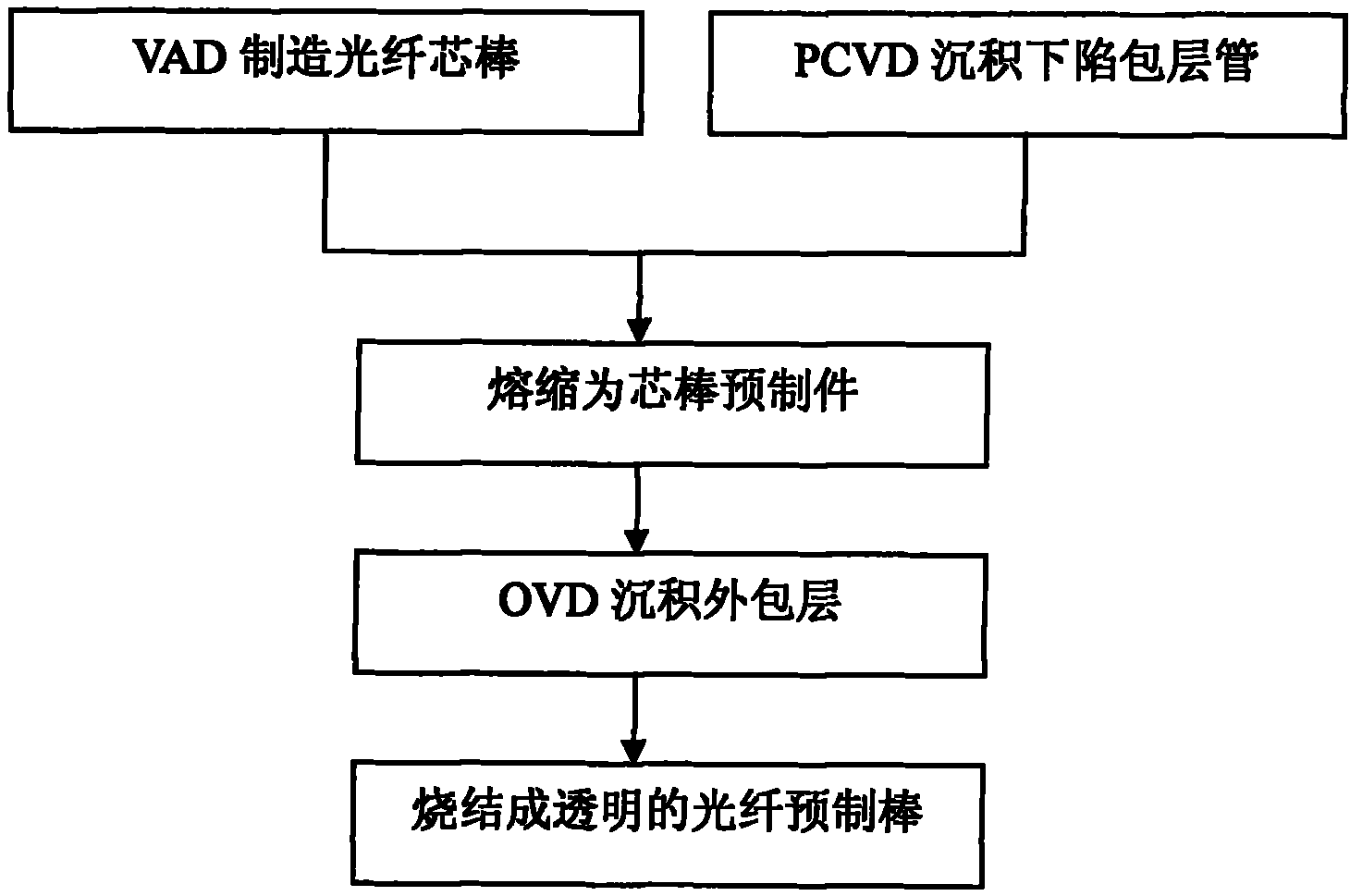
Preparation method of optical fiber preform
An optical fiber preform and a manufacturing method technology, which are applied in the directions of manufacturing tools, glass manufacturing equipment, glass fiber products, etc., can solve the problems of unguaranteed optical fiber performance, waste of optical fiber raw materials, low fluorine deposition efficiency, etc., and achieve good application prospects. and economic and social benefits, improve manufacturing efficiency, and improve the effect of deposition efficiency
- Summary
- Abstract
- Description
- Claims
- Application Information
AI Technical Summary
Problems solved by technology
Method used
Image

Examples
Embodiment 1
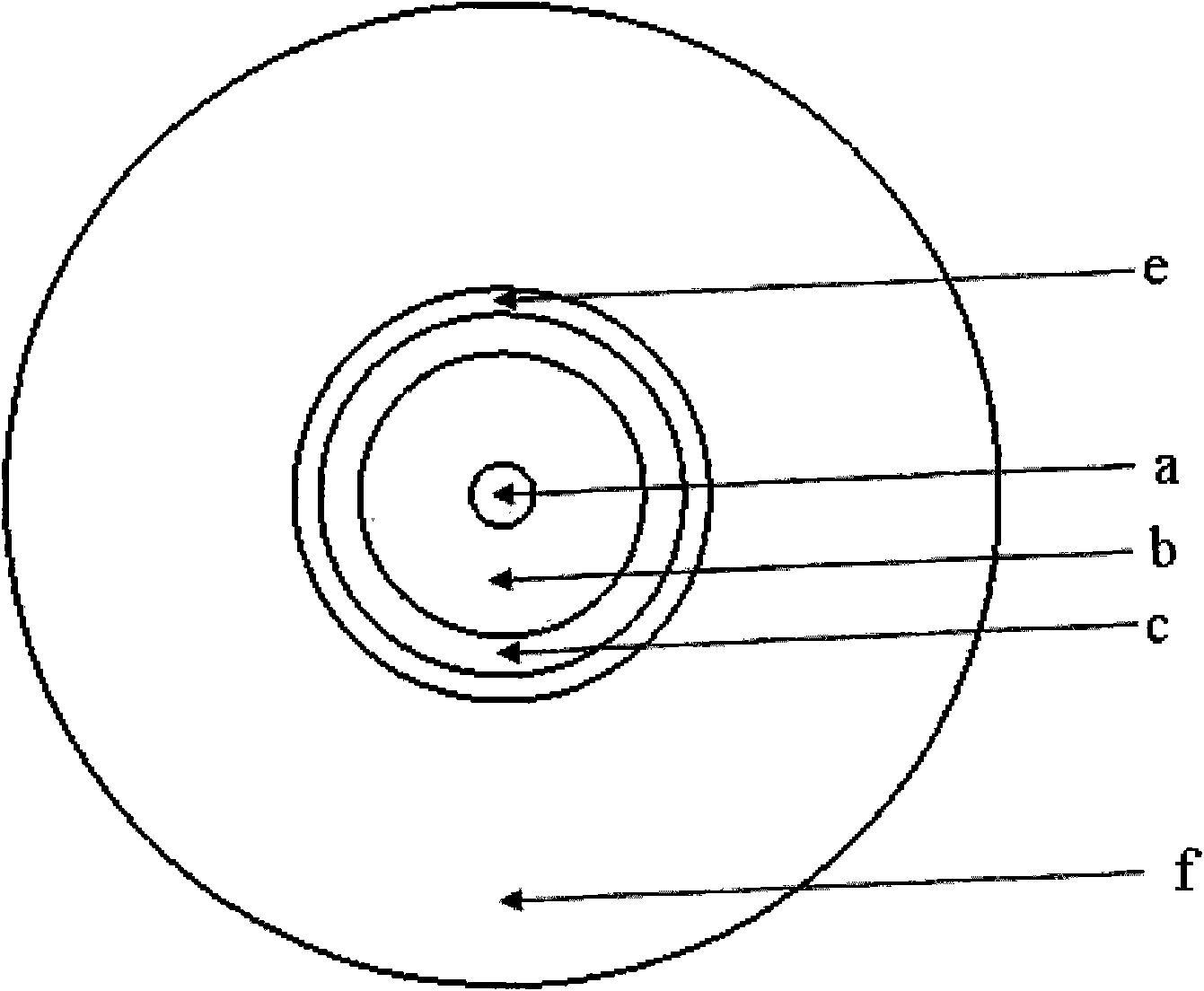
[0053] A target rod with a diameter of 50 mm is placed on a VAD deposition lathe, and a mixed gas of silicon tetrachloride, germanium tetrachloride and high-purity oxygen is introduced to form a germanium-doped quartz glass core layer at a high temperature in an oxygen-hydrogen flame (see figure 2 part a in ) and partial cladding (see figure 2 Part b in), the total flow rate of the mixed gas is 12500ml / min, and the deposition rate of the core rod is 9.8g / min to form an optical fiber core rod. The diameter of the optical fiber core rod is 32mm, and the diameter of the core layer is 8mm. The relative refractive index difference between some and pure quartz glass is 0.33%.
[0054] A pure quartz glass substrate tube with an outer diameter of 58.5 mm and an inner diameter of 52.5 mm was placed on a PCVD deposition lathe, and silicon tetrachloride, C 2 f 6 Mixed gas with high-purity oxygen, the total flow rate of the mixed gas is 8500ml / min, under the action of 9.6kW microwave,...
Embodiment 2
[0062] A target rod with a diameter of 70 mm is placed on a VAD deposition lathe, and a mixed gas of silicon tetrachloride, germanium tetrachloride and high-purity oxygen is introduced to form a germanium-doped quartz glass core layer at a high temperature in an oxygen-hydrogen flame (see figure 2 part a in ) and partial cladding (see figure 2 Part b in), the total flow rate of the mixed gas is 18000ml / min, the deposition rate of the fiber core rod is 18.5g / min, forming the fiber core rod, the diameter of the fiber core rod is 60mm, wherein the diameter of the core layer is 15mm, the core The relative refractive index difference between the layer portion and pure silica glass is 0.42%.
[0063] A pure quartz glass substrate tube with an outer diameter of 80 mm and an inner diameter of 76 mm was placed on a PCVD deposition lathe, and silicon tetrachloride, C 2 f 6 Mixed gas with high-purity oxygen, the total flow rate of the mixed gas is 9500ml / min, under the action of 13.8...
Embodiment 3
[0070] A target rod with a diameter of 60 mm is placed on a VAD deposition lathe, and a mixed gas of silicon tetrachloride, germanium tetrachloride and high-purity oxygen is introduced to form a germanium-doped quartz glass core layer at a high temperature in an oxygen-hydrogen flame (see figure 2 part a in ) and partial cladding (see figure 2 b part in), the total flow rate of the mixed gas is 13600ml / min, the deposition rate of the optical fiber core rod is 12g / min, forming the optical fiber core rod, the diameter of the optical fiber core rod is 40.2mm, wherein the diameter of the core layer is 9.9mm, The relative refractive index difference between the core layer and pure silica glass is 0.36%.
[0071]A pure quartz glass substrate tube with an outer diameter of 58.5 mm and an inner diameter of 52.5 mm was placed on a PCVD deposition lathe, and silicon tetrachloride, C 2 f 6 Mixed gas with high-purity oxygen, the total flow rate of mixed gas is 8800ml / min, under the ac...
PUM
| Property | Measurement | Unit |
|---|---|---|
| diameter | aaaaa | aaaaa |
| diameter | aaaaa | aaaaa |
| diameter | aaaaa | aaaaa |
Abstract
Description
Claims
Application Information