
Double-blade single-shaft centrifugal pump

A centrifugal pump and double-blade technology, which is applied in the field of centrifugal pumps, can solve the problems of reduced service time of centrifugal pumps, increased pressure of centrifugal pumps, and easy clogging, so as to reduce the clogging of centrifugal pumps by sediment, reduce the probability of damage, and improve dilution degree of effect

Pending Publication Date: 2021-08-31
许青华
View PDF1 Cites 0 Cited by
  • Summary
  • Abstract
  • Description
  • Claims
  • Application Information

AI Technical Summary

Problems solved by technology

[0004] In the sandy basin of the Yellow River in my country, centrifugal pumps are used to pump water for farmland irrigation. However, due to the large amount of sediment in the river water, the centrifugal pump is prone to blockage during the pumping process. After the centrifugal pump is blocked, the water flow Under the action of the centrifugal force generated by the high-speed operation of the centrifugal pump, it is pumped into the interior of the centrifugal pump, resulting in an increase in the internal pressure of the centrifugal pump, which is likely to cause damage to the centrifugal pump and reduce the service life of the centrifugal pump. At the same time, the connection between the centrifugal pump and the water pipe Water leakage is prone to occur everywhere. During the working process of the centrifugal pump, the staff cannot find the water leakage in time, which leads to the waste of water resources and more serious water leakage.

Method used


Image

  • Double-blade single-shaft centrifugal pump
  • Double-blade single-shaft centrifugal pump
  • Double-blade single-shaft centrifugal pump

Examples


Embodiment Construction

[0034] The following will clearly and completely describe the technical solutions in the embodiments of the present invention with reference to the accompanying drawings in the embodiments of the present invention. Obviously, the described embodiments are only some, not all, embodiments of the present invention. Based on the embodiments of the present invention, all other embodiments obtained by persons of ordinary skill in the art without making creative efforts belong to the protection scope of the present invention.

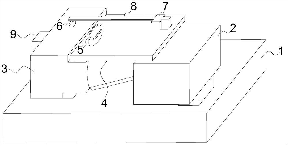
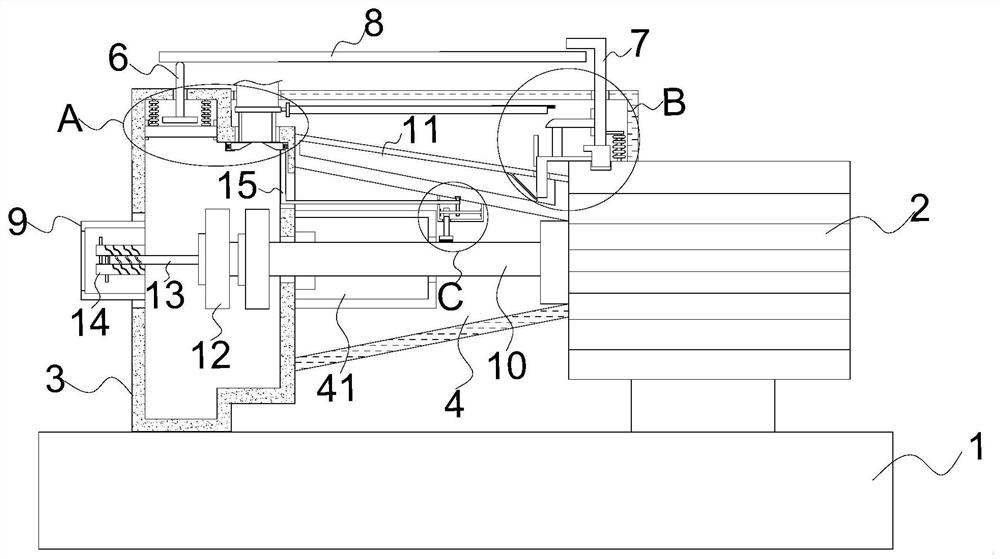
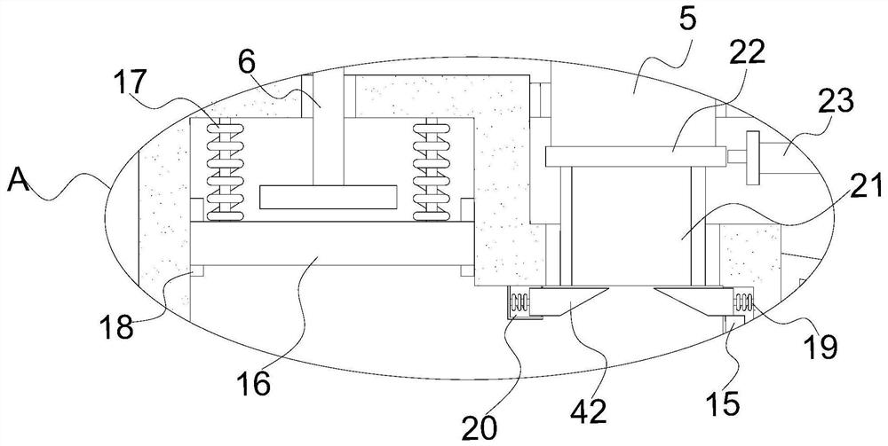
[0035] see Figure 1 to Figure 10 , the present invention provides a technical solution:

[0036] A double-vane single-shaft centrifugal pump, such as Figure 1 to Figure 4 as well as Figure 7 and Figure 10 As shown, it includes a base 1, a driving motor 2 and a housing 3, the bottom of the driving motor 2 is fixedly connected to the top right side of the base 1, and the bottom of the housing 3 is fixedly connected to the top left side of the base 1, so ...


PUM


Abstract

The invention relates to the technical field of centrifugal pumps, in particular to a double-blade single-shaft centrifugal pump. The double-blade single-shaft centrifugal pump comprises a base, a driving motor and a shell. The bottom of the driving motor is fixedly connected with the right side of the top of the base. The bottom of the shell is fixedly connected with the left side of the top of the base. A water inlet pipe is fixedly connected to the center of the left side of the shell. A water outlet pipe is fixedly connected to the center of the right side of the top of the shell. A fixing frame is fixedly connected between the driving motor and the shell. The output end of the driving motor is fixedly connected with a first rotating shaft. A connecting frame is fixedly connected to the center of the right side of the shell. According to the double-blade single-shaft centrifugal pump, through cooperative use of a detection rod, a push block and a control button, the driving motor can be automatically turned off when the centrifugal pump is blocked and the internal pressure intensity of the centrifugal pump is too large, and therefore the probability that the centrifugal pump is damaged can be effectively reduced; and meanwhile, when the centrifugal pump leaks water, the centrifugal pump is automatically turned off, and waste of water resources is reduced.

Description

technical field [0001] The invention relates to the technical field of centrifugal pumps, in particular to a double-vane single-shaft centrifugal pump. Background technique [0002] A centrifugal pump refers to a pump that delivers liquid by the centrifugal force generated when the impeller rotates. Before the pump is started, the pump casing and the suction pipe must be filled with water, and then the motor is started to drive the pump shaft to drive the impeller and water to rotate at high speed. Centrifugal movement occurs, thrown to the outer edge of the impeller, and flows into the pressure water pipeline of the water pump through the flow channel of the volute pump casing. [0003] Existing patent (notification number: CN110821842B) a working wheel and a centrifugal pump for a centrifugal pump, discloses a working wheel and a centrifugal pump for a centrifugal pump, including a servo motor, the left side of the servo motor is provided with Working wheel, said working ...

Claims


Application Information

Patent Timeline
Patent Type & Authority Applications(China)
IPC IPC(8): F04D15/00F04D13/06F04D29/00F04D29/06
CPCF04D13/06F04D15/0077F04D29/007F04D29/061
Inventor 许青华李俊杰
Owner 许青华
Learn More