

Centrifugal microfluidic detection device and centrifugal microfluidic detection system
A detection device and microfluidic technology, applied in measurement devices, instruments, material analysis by optical means, etc., can solve the problem of inability to use immunodetection or nucleic acid detection, and can not do chemiluminescence detection lateral flow immunoassay test strip imaging Detection and other problems to achieve the effect of improving detection performance and improving versatility
- Summary
- Abstract
- Description
- Claims
- Application Information
AI Technical Summary
Problems solved by technology
Method used
Image

Examples
Embodiment Construction
[0058] The following will clearly and completely describe the technical solutions in the embodiments of the present invention with reference to the accompanying drawings in the embodiments of the present invention. Obviously, the described embodiments are only some, not all, embodiments of the present invention. Based on the embodiments of the present invention, all other embodiments obtained by persons of ordinary skill in the art without making creative efforts belong to the protection scope of the present invention.
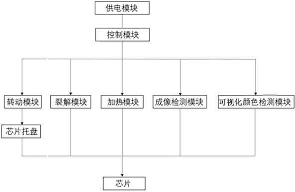
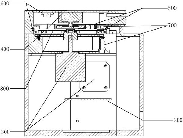
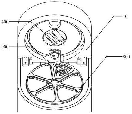
[0059] Such as Picture 1-1 As shown in 1, the centrifugal microfluidic detection device provided by the embodiment of the present invention includes: a power supply module 100, a control module 200, a rotation module 300, a cracking module 400, a heating module 500, an imaging detection module 600, a visual color detection module 700, and Chip tray 800.
[0060] In the above-mentioned centrifugal microfluidic detection device, the chip tray 800 is used to ca...
PUM
 Abstract
Description
Claims
Application Information