
Fiber End Caps and Fiber Lasers

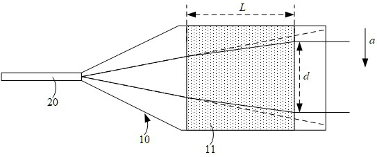
A fiber end and end cap technology, which is applied in the field of lasers, can solve the problems of increased overall volume of fiber end caps and complex optical systems, and achieve the effects of reducing processing and manufacturing costs, reducing overall volume, and simplifying the structure

Active Publication Date: 2021-10-15
LASER FUSION RES CENT CHINA ACAD OF ENG PHYSICS
View PDF25 Cites 0 Cited by
  • Summary
  • Abstract
  • Description
  • Claims
  • Application Information

AI Technical Summary

Problems solved by technology

In order to obtain collimated beams, focused beams or divergent beams, the traditional way is to set an additional lens group at the output end of the fiber end cap, so that the beams can be collimated, focused or diverged through the lens group. In this way, it is bound to The increase in the overall volume of the fiber end cap makes the optical system more complex

Method used


Image

  • Fiber End Caps and Fiber Lasers
  • Fiber End Caps and Fiber Lasers
  • Fiber End Caps and Fiber Lasers

Examples


Embodiment Construction

[0034] In order to make the purpose, technical solutions and advantages of the embodiments of the present invention clearer, the technical solutions in the embodiments of the present invention will be clearly and completely described below in conjunction with the drawings in the embodiments of the present invention. Obviously, the described embodiments It is a part of embodiments of the present invention, but not all embodiments. The components of the embodiments of the invention generally described and illustrated in the figures herein may be arranged and designed in a variety of different configurations.

[0035] Accordingly, the following detailed description of the embodiments of the invention provided in the accompanying drawings is not intended to limit the scope of the claimed invention, but merely represents selected embodiments of the invention. Based on the embodiments of the present invention, all other embodiments obtained by persons of ordinary skill in the art wi...


PUM


Abstract

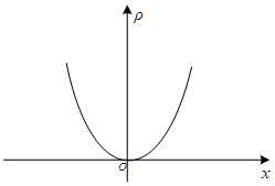
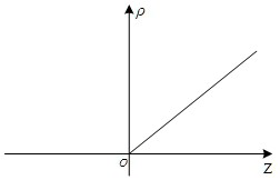
An optical fiber end cap and an optical fiber laser relate to the technical field of lasers. The fiber end cap includes an end cap body and an ion-doped region located in the end cap body, the light incident side of the end cap body is used for fusion splicing with the output end of the energy transmission fiber of the fiber laser; the beam emitted from the energy transmission fiber enters the end cap In the body, the transmission path of the light beam can be changed through the ion-doped region. The fiber laser includes the above-mentioned fiber end cap. The optical fiber end cap can change the refractive index of the end cap body, so that the light beam can output a light beam with specific optical characteristics after passing through the end cap body.

Description

technical field [0001] The invention relates to the technical field of lasers, in particular to an optical fiber end cap and an optical fiber laser. Background technique [0002] High-power fiber lasers have broad application prospects in industrial processing, medical treatment, national defense and other technical fields due to their high efficiency, high stability, high beam quality, long life, and easy expansion to high power. Because high-power fiber lasers usually use double-clad fiber technology, their cores are generally small, so the power density at the output end of high-power fiber lasers is high, and small end-face contamination or processing defects will cause damage to the end face of the fiber. [0003] In order to reduce the power density at the output end of the fiber, the most commonly used solution at present is to weld a fiber end cap on the end face of the energy-transmitting fiber of the fiber laser. At present, the design feature of the fiber end cap...

Claims


Application Information

Patent Timeline
Patent Type & Authority Patents(China)
IPC IPC(8): G02B6/26G02B6/25
CPCG02B6/25G02B6/262
Inventor 李敏沈本剑陶汝茂刘玙吴文杰冯曦黄珊宋华青谢亮华李昊坤张春高聪林宏奂王建军
Owner LASER FUSION RES CENT CHINA ACAD OF ENG PHYSICS
Learn More