Test device with electromagnetic shielding and capable of releasing melt

A technology of electromagnetic shielding and testing equipment, which is applied in the field of testing equipment for molten materials and testing equipment for releasing molten materials with electromagnetic shielding. Simulation test vitrification treatment and other issues

Inactive Publication Date: 2021-08-31
深圳市赛迈特新材料有限公司
View PDF10 Cites 1 Cited by
  • Summary
  • Abstract
  • Description
  • Claims
  • Application Information

AI Technical Summary

Problems solved by technology

According to the melt test device with lifting chassis of the present invention, multiple melt-related test studies can be carried out, and after the test, the molten pool and its upper shell structure can be completely removed. The melt test device includes a water cooling jacket Tube, induction heating coil and chassi

Method used


Image

  • Test device with electromagnetic shielding and capable of releasing melt
  • Test device with electromagnetic shielding and capable of releasing melt
  • Test device with electromagnetic shielding and capable of releasing melt

Examples


Embodiment 1

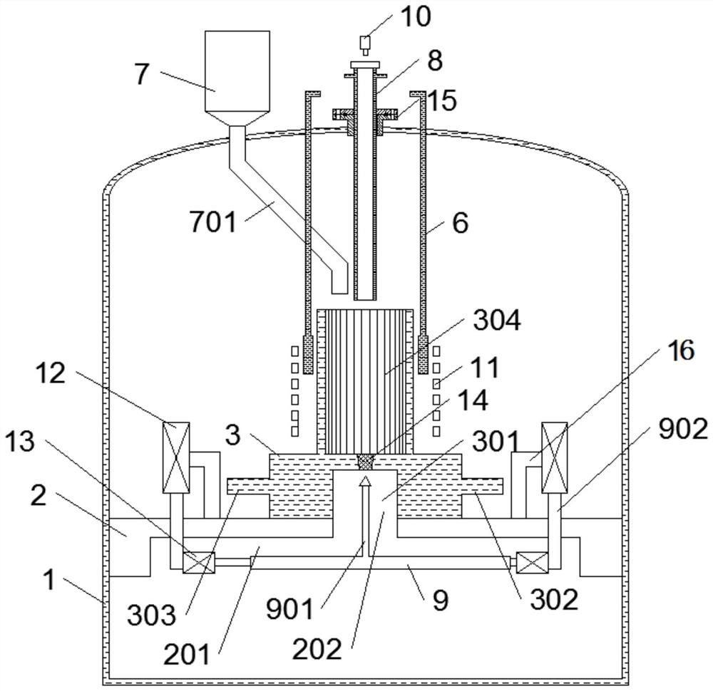
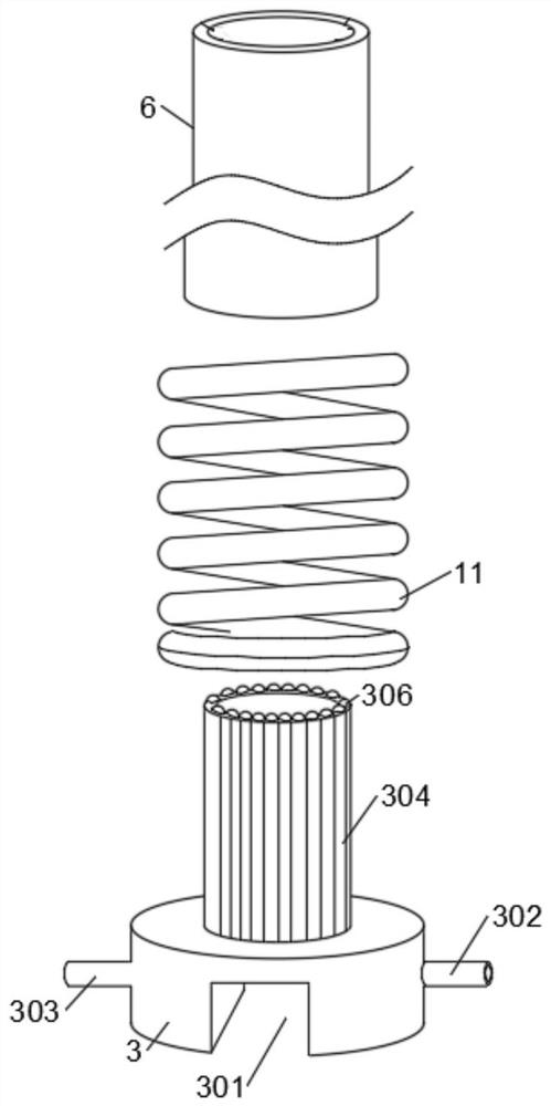
[0058] like Figure 1-Figure 6 As shown, a test device with electromagnetic shielding and releasable melt provided in this embodiment includes a furnace body of the device, a base support is fixed inside the furnace body of the device, and the upper side of the base support is provided with A cold crucible, the cold crucible is provided with a crucible body, an induction coil is sleeved on the crucible body, and an electromagnetic shielding device that can move along the axis of the crucible is arranged between the induction coil and the crucible body; the crucible body is Water-cooled tubes and refractory filling materials.

[0059] Through the above technical solution, the crucible body is composed of water-cooled tubes and refractory filling materials, instead of dividing the crucible chassis and crucible body, so the structure is simple, the effect of melting is obvious, and the efficiency of detection and the convenience of use are improved.

Embodiment 2

[0061] The induction coil is sleeved on the periphery of the crucible body, the induction coil is connected to the external cooling circulation system through a water pipe, and there is a gap between the induction coil and the crucible body, the gap is to ensure that the electromagnetic shielding device can Move up and down along the axis of the crucible.

[0062] The induction coil is made of copper tube, with cooling water inside, coiled on the outside of the crucible body, and converts the high-frequency alternating current generated by the power supply into a high-frequency alternating electromagnetic field, and then heats and melts the test working medium in the cold crucible, simulating the interior of the melt pool heat source.

[0063] Further, the crucible body is cylindrical, and the outer circumference of the crucible body is arranged with several first water-cooled tubes and second water-cooled tubes, each of the first water-cooled tubes and each of the second wate...

Embodiment 3

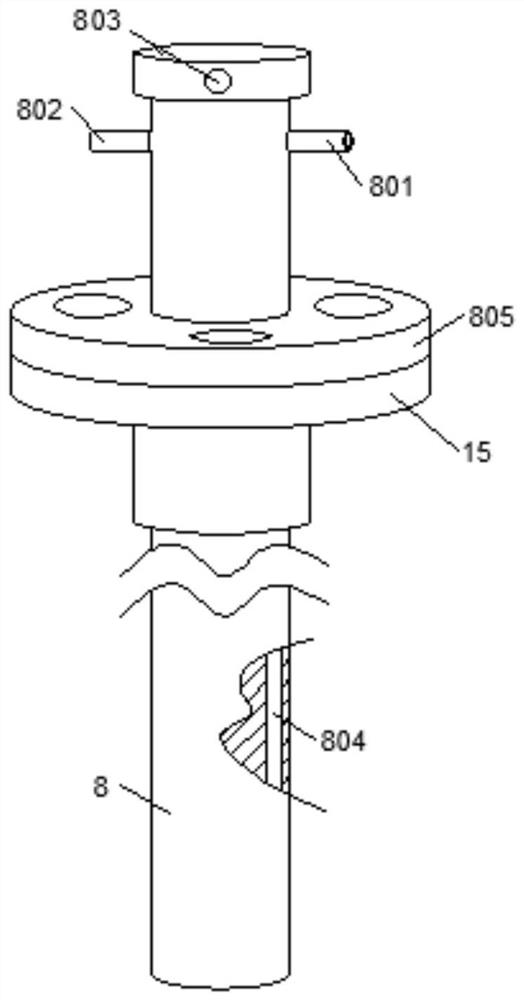
[0067] The bottom of the cold crucible is provided with a cold crucible release groove, the center of the bottom of the cold crucible is provided with a discharge hole, the inside of the discharge hole is provided with a plug, and the bottom of the discharge hole is provided with a release mechanism , the release mechanism is fixedly provided with a thimble rod on the same vertical axis as the plug;

[0068] The release mechanism includes a longitudinal push rod, a longitudinal telescopic machine, a horizontal push rod, a horizontal telescopic machine and a thimble bar, and two of the longitudinal telescopic machine, the horizontal telescopic machine and the longitudinal push rod are provided, and the longitudinal push One end of the rod is connected to the longitudinal telescopic machine, the other end of the longitudinal push rod is connected to the horizontal push rod, and the horizontal telescopic machine is also arranged on the longitudinal push rod, and the horizontal tel...


PUM


Abstract

The invention relates to the technical field of thermoengineering, in particular to a test device with electromagnetic shielding and capable of releasing melt. The test device comprises a furnace body; a base support part is arranged in the furnace body; a cold crucible is arranged on the upper side surface of the base support part; a crucible body is arranged on the cold crucible; an induction coil sleeves the crucible body; an electromagnetic shielding device is arranged between the induction coil and the crucible body; an argon blowing device is arranged over the crucible body; a discharge hole is formed between the cold crucible release groove and the crucible body; and a release mechanism is arranged below the discharge hole. A plug is jacked open by controlling rapid lifting of an ejector pin rod, and then the ejector pin rod is controlled to horizontally move away from the position under the discharge hole. The argon blowing device is of a double-layer structure, and cooling water is introduced into the argon blowing device to prevent damage by high temperature. The cold crucible is of an integrated structure, and the sealing performance and safety of the whole device are improved. The electromagnetic shielding device can move in the axial direction of the crucible, and the position and thickness of a kish or the interface of reactants are controlled by controlling the lifting of the shielding device.

Description

technical field [0001] The invention relates to a test device for molten matter, in particular to a test device for releasing molten matter with electromagnetic shielding, and belongs to the technical field of thermal engineering. Background technique [0002] When a serious accident occurs in a pressurized water reactor in a nuclear power plant, if the core cannot be effectively cooled, the core will melt, and the high-temperature core melt may fall into the lower head of the pressure vessel and form in the lower head of the pressure vessel. The molten pool structure, under the action of the decay heat of the core melt, the high-temperature molten pool transfers heat to the wall of the lower head of the pressure vessel, resulting in an increase in the temperature of the wall of the lower head of the pressure vessel, which seriously threatens the integrity of the pressure vessel. If the wall of the lower head of the vessel cannot effectively dissipate the decay heat in the m...

Claims


Application Information

Patent Timeline
IPC IPC(8): G21C17/00
CPCG21C17/001Y02E30/30
Inventor 方智焦大伟陈朝牛
Owner 深圳市赛迈特新材料有限公司
Why Eureka
Try Eureka