A swivel track-changing crane

A technology of cranes and swivels, which is applied in the direction of cranes, trolley cranes, mechanical equipment, etc., can solve the problems of reducing friction, cable breakage, wear, etc., and achieve the effects of reducing wear, increasing service life, and reducing friction

Active Publication Date: 2022-04-08
河南省新东方起重机集团有限公司
View PDF7 Cites 0 Cited by
  • Summary
  • Abstract
  • Description
  • Claims
  • Application Information

AI Technical Summary

Problems solved by technology

[0005] The object of the present invention is to provide a swivel rail-changing crane, which can evenly wind the steel rope on the winding roller by setting a uniform rope winding mechanism, and effectively lubricate the surface of the steel rope by setting a lubrication mechanism, reducing the speed of the winding process. The frictional force of the middle cable can reduce the wear of the cable and improve the service life of the cable. The rail change operation is realized by setting the steering mechanism and the jack. Evenly wound on the winding roller, and the steel cable is easy to wear due to friction during the retracting and unwinding process, which will lead to the breakage of the steel cable in the long run, and it is more troublesome when the crane is changing the track

Method used


Image

  • A swivel track-changing crane
  • A swivel track-changing crane
  • A swivel track-changing crane

Examples


Embodiment 1

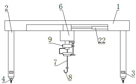
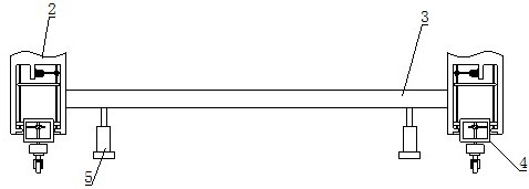
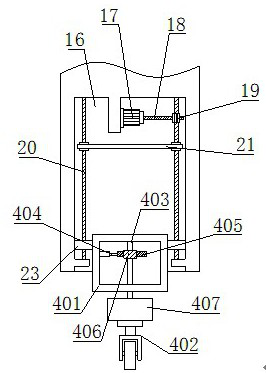
[0037] Such as Figure 1-9 As shown, a kind of swivel rail changing crane that the present invention proposes comprises main beam 1, support beam 2, longitudinal beam 3, steel cable 7, suspension hook 8 and push-pull cylinder 22, and the bottom of main beam 1 is fixedly installed with bolt Four sets of supporting beams 2 and longitudinal beams 3 are fixedly connected to two supporting beams 2 on the same side by bolts. The supporting beams 2 support the crane. Jacks 5 are installed on the bottom of the longitudinal beams 3, and the jacks 5 are used to lift the longitudinal beams 3. The bottom of the support beam 2 is equipped with a steering traveling mechanism 4, which is used for the walking of the crane. The steering traveling mechanism 4 includes a driving box 401, an electric traveling wheel 402, a steering shaft 403, an electric push rod 404, and a first rack 405 , the first gear 406 and the fixed block 407; the drive box 401 is arranged on the bottom of the support beam...

Embodiment 2

[0042] Such as image 3 As shown, this embodiment is basically the same as Embodiment 1. Preferably, the bottom of the support beam 2 is provided with a storage slot 16, and a second drive motor 17 is fixedly installed in the storage slot 16 through a motor seat; the storage slot 16 is rotated by a bearing. There are many sets of studs 20, each stud 20 is provided with a sprocket, each stud 20 is connected by transmission chain 21, and the transmission chain 21 drives each stud 20 to rotate synchronously; the output end of the second driving motor 17 is installed There is a worm 18, and the second drive motor 17 is used to drive the worm 18, wherein a set of studs 20 is provided with a worm gear 19, the worm 18 is meshed with the worm gear 19, and the worm 18 drives the worm gear 19 to rotate; the outer wall of the drive box 401 is fixed by bolts There are many sets of moving blocks 23 installed, the moving blocks 23 correspond to the studs 20 one by one, and the moving blocks...

Embodiment 3

[0044] Such as Figure 10-12 As shown, this embodiment is basically the same as Embodiment 1. Preferably, the outer peripheral surface of the standpipe 901 is fixed with a fixed bracket 15 by bolts, and the other end of the fixed bracket 15 is fixedly connected to the cleaning mechanism 10 by bolts. The surface of the cable 7 is cleaned to remove the dust particles on the surface of the cable 7, which is helpful for the subsequent lubrication operation, and also helps to reduce the friction force received by the cable 7 when it moves, and reduces the impact on the cable 7 due to friction. damage; the cleaning mechanism 10 includes a fixed ring 1001, a rotating ring 1002, a second external gear ring 1003, an arc-shaped mouth 1004, a slide bar 1005, a cleaning brush 1006, a pin rod 1007 and a limit slot 1008; the fixed ring 1001 and the fixed Support 15 is fixedly connected, and rotating ring 1002 is arranged on the bottom of fixed ring 1001. Multiple sets of limit slots 1008, ...


PUM


Abstract

The invention belongs to the technical field of cranes, and is used to solve the problem that the steel cables of the existing cranes cannot be evenly wound on the winding rollers, and the steel cables are easily worn due to the action of friction during the retracting and unwinding process, which will cause the steel cables to break if things go on like this. And it is a more troublesome problem when the crane is changing rails, specifically a swivel rail changing crane, including a main beam, a support beam is installed at the bottom of the main beam, a jack is installed at the bottom of the longitudinal beam, and a steering wheel is installed at the bottom of the support beam. In the walking mechanism, the bottom of the main beam is provided with a uniform rope winding mechanism, and the push-pull cylinder acts on the uniform rope winding mechanism, and a lubrication mechanism is provided below the uniform rope winding mechanism; The wire rope is evenly wound on the winding roller, and the surface of the wire rope is effectively lubricated by the lubricating mechanism to reduce the wear of the wire rope, and the rail changing operation of the crane is relatively simple and convenient.

Description

technical field [0001] The invention relates to the technical field of cranes, in particular to a swivel rail-changing crane. Background technique [0002] A crane refers to a multi-action hoisting machine that lifts vertically and transports heavy objects horizontally within a certain range. It is also called a crane, an aerial crane, and a crane. etc. The hoisting mechanism is the basic working mechanism of the crane, mostly composed of a suspension system and a winch, and some lift heavy objects through a hydraulic system. The operating mechanism is used to move heavy objects vertically and horizontally or adjust the working position of the crane, generally It is composed of motor, reducer, brake and wheels. The luffing mechanism is only equipped on the jib crane. The amplitude decreases when the jib is raised up, and the amplitude increases when it is lowered. It is divided into two types: balanced luffing and unbalanced luffing. , the slewing mechanism is used to turn ...

Claims


Application Information

Patent Timeline
Patent Type & Authority Patents(China)
IPC IPC(8): B66C5/02B66C19/00B66D1/12B66D1/28B66D1/36F16N11/00B08B1/00
CPCB66C19/00B66C5/02B66D1/12B66D1/36B66D1/28F16N11/00B08B1/002
Inventor 徐庆贺路祥龙宋雯雯付春彪魏军凯
Owner 河南省新东方起重机集团有限公司
Why Eureka
Try Eureka