Integrated air supplying and exhausting fan

A technology for supplying and exhausting air and fans, applied in the field of machinery, can solve the problems of increasing the number of air valves and fans in the pipeline, increasing the maintenance cost, complex structure, etc., and achieving the effects of convenient maintenance, simple structure, and flexible operation and operation.

Pending Publication Date: 2021-09-03
XIAN THERMAL POWER RES INST CO LTD
View PDF8 Cites 0 Cited by
  • Summary
  • Abstract
  • Description
  • Claims
  • Application Information

AI Technical Summary

Problems solved by technology

However, at present, the air supply and exhaust pipelines are designed to be arranged independently for the room, with one supply fan or one exhaust fan, or both supply and exhaust fans. This method requires at least two ventilation holes in the room. more complicated structure
In order to achieve the required air exchange volume and room pressure, joint debugging of the air supply and exhaust pipelines is required at the same time, which is difficult
In addition, this arrangement increases the number of pipes, air valves and fans, increasing maintenance costs

Method used


Image

  • Integrated air supplying and exhausting fan
  • Integrated air supplying and exhausting fan
  • Integrated air supplying and exhausting fan

Examples


Embodiment 1

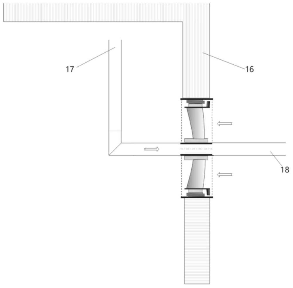
[0029] When it is necessary to create a positive pressure in the room, the fan is installed as image 3 As shown, the suction port connecting pipe 17 is connected to the air exhaust port connecting pipe 18 through the fan inner pipe 10, the outer casing 1 is fixed in the through hole on the wall 16 of the room of the structure, and the side between the outer casing 1 and the fan inner pipe 10 An air inlet protection net 14 is provided, and an air outlet protection net 15 is provided on the other side between the outer casing 1 and the fan inner pipe 10 .

[0030] When working, the fan blades 7 send air into the room, so that the room forms a positive pressure, and the positive pressure in the room makes the gas at the top of the room flow into the air inlet connecting pipe 17, and then enter the air outlet connecting pipe 18 through the fan inner pipe 10 In the middle, and finally out of the room, when working, this way of working can remove the light gas at the top of the roo...

Embodiment 2

[0032] When it is necessary to form a negative pressure in the room, the fan is installed as Figure 4 As shown, specifically, the air inlet connecting pipe 21 communicates with the air outlet connecting pipe 22 through the fan inner pipe 10, and the outer shell 1 is fixed in the through hole on the wall 16 of the room of the structure.

[0033] The gas in the room is discharged through the fan blades 7 to form a negative pressure, and the negative pressure in the room makes the outside air flow into the fan inner pipe 10 through the air inlet connecting pipe 21, and then enter the room through the air outlet connecting pipe 22.

Embodiment 3

[0035] When the fan is not conducive to being installed on the wall or needs to be moved, it can be used in conjunction with the sleeve-type air duct assembly. The fan inner pipe 19 in the sleeve-type air duct assembly is docked with the fan inner pipe 10. The installation of the fan and the sleeve like Figure 5 As shown, specifically, in the sleeve-type air duct assembly, the fan outer shell 20 is docked with the outer shell 1, the fan inner pipe 19 is docked with the fan inner pipe 10, and the sleeve-type air duct can be installed on both sides of the fan. Through the above-mentioned different configuration combinations, the positive and negative pressure control of the room can be realized, and the arrangement of air inlets or exhaust outlets at different positions in the room can also be realized, which has strong operational flexibility.

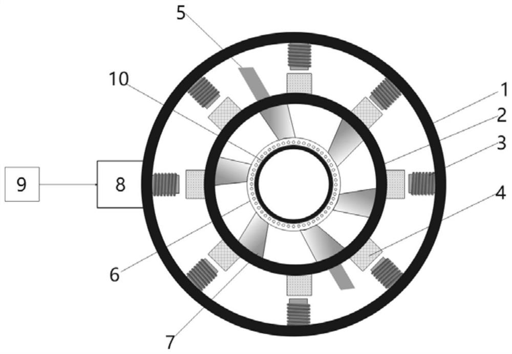
[0036] The power supply system 9 is connected to the stator core and the winding 3 through the junction box 8, and generates a rotati...


PUM


Abstract

The invention discloses an integrated air supplying and exhausting fan. The integrated air supplying and exhausting fan comprises an outer shell, a rotor base body, a bearing part, a power supply system, a fan inner pipe, a plurality of stator iron cores and windings, a plurality of fan blades and a plurality of permanent magnet poles, wherein the outer shell, the rotor base body, the bearing part and the fan inner pipe are sequentially distributed from outside to inside; the stator iron cores and windings are sequentially fixed on the inner wall of the outer shell; the permanent magnet poles are sequentially fixed on the outer wall of the rotor base body; the bearing part is fixed on the outer wall of the fan inner pipe; one end of each fan blade is connected with the inner wall of the rotor base body; the other end of each fan blade is connected with the bearing part to form a ring-shaped air flowing channel; and the power supply system is connected with the windings in the the stator iron cores and windings. The integrated air supplying and exhausting fan is low in maintenance cost and simple in structure.

Description

technical field [0001] The invention belongs to the field of machinery and relates to an integrated air supply and exhaust fan. Background technique [0002] Ventilation fan is suitable for all walks of life. Through mechanical ventilation, it can play the role of ventilation and cooling in the room. Through ventilation and ventilation, the gas in the room can be updated at a certain ventilation rate, which can maintain fresh air and reduce the temperature of the room. Harmful gas concentration and other effects are especially suitable for structures that may generate harmful gases, such as battery rooms, hydrogen storage rooms, and radioactive waste storage rooms. However, at present, the air supply and exhaust pipelines are designed to be arranged independently for the room, with one supply fan or one exhaust fan, or both supply and exhaust fans. This method requires at least two ventilation holes in the room. The structure is more complicated. In order to achieve the re...

Claims


Application Information

Patent Timeline
Patent Type & Authority Applications(China)
IPC IPC(8): F04D25/08F04D29/52F04D29/70F24F7/013F24F13/02H02K9/06H02K5/22H02K1/27
CPCF04D25/08F04D29/522F04D29/703F24F7/013F24F13/02H02K9/06H02K5/225H02K1/274
Inventor 武方杰姚尧张瑞祥王彤刘俊峰徐海龙陈振平
Owner XIAN THERMAL POWER RES INST CO LTD
Why Eureka
Try Eureka