Pressure sensor based on ceramic resistor sensing technology

A technology of pressure sensor and sensing technology, which is applied in the direction of fluid pressure measurement, measurement of fluid pressure, and instruments by changing ohmic resistance, can solve the problems of inability to collect, waste energy, drift, etc., to reduce processing difficulty and production cost, The effect of widening the operating temperature range and reducing the effect of accuracy

Pending Publication Date: 2021-09-03
布瑞特智联科技(杭州)有限公司
View PDF0 Cites 0 Cited by
  • Summary
  • Abstract
  • Description
  • Claims
  • Application Information

AI Technical Summary

Problems solved by technology

For example, in the automobile air-conditioning industry, traditional automobiles use pressure switches to determine the operation or stop of the system by collecting a certain pressure value of the refrigerant in the pipeline. This simple and crude control method is not only inefficient, but also wastes energy and is easy to damage the system. replaced by a pressure sensor
In addition, the traditional pressure sensor based on MEMS and ceramic capacitor technology will have serious drift due to the influence of temperature, especially in the case of high temperature and low temperature, the error will increase significantly, so that high-precision data acquisition cannot be carried out in the whole temperature range
This patent develops a pressure sensor based on ceramic resistance sensing technology, which can replace the traditional pressure switch to achieve precise control, and can also overcome the problem that traditional pressure sensors cannot achieve data acquisition in the full temperature range

Method used


Image

  • Pressure sensor based on ceramic resistor sensing technology
  • Pressure sensor based on ceramic resistor sensing technology
  • Pressure sensor based on ceramic resistor sensing technology

Examples


Embodiment Construction

[0025] The technical solutions of the present invention will be clearly and completely described below in conjunction with the accompanying drawings. Apparently, the described embodiments are part of the embodiments of the present invention, but not all of them. Based on the embodiments of the present invention, all other embodiments obtained by persons of ordinary skill in the art without making creative efforts belong to the protection scope of the present invention.

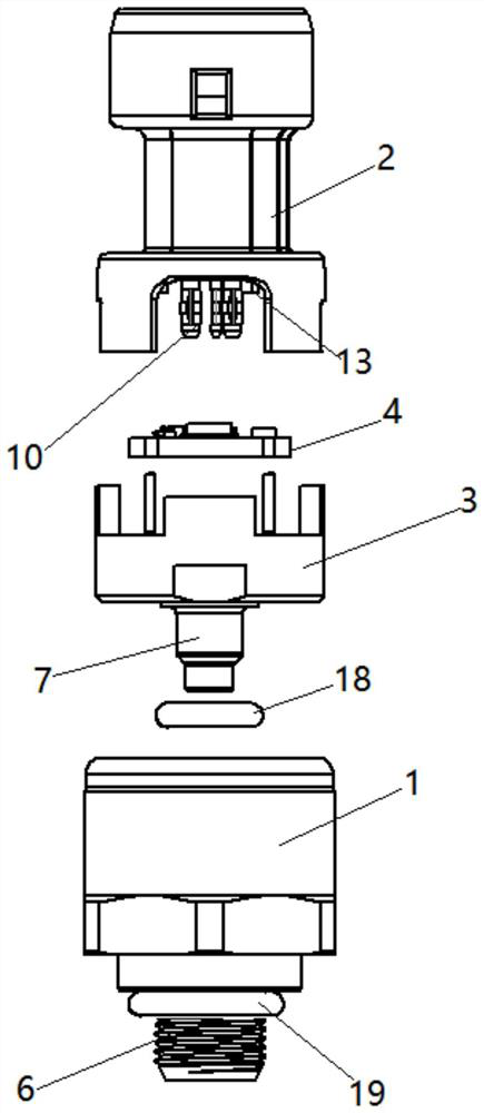
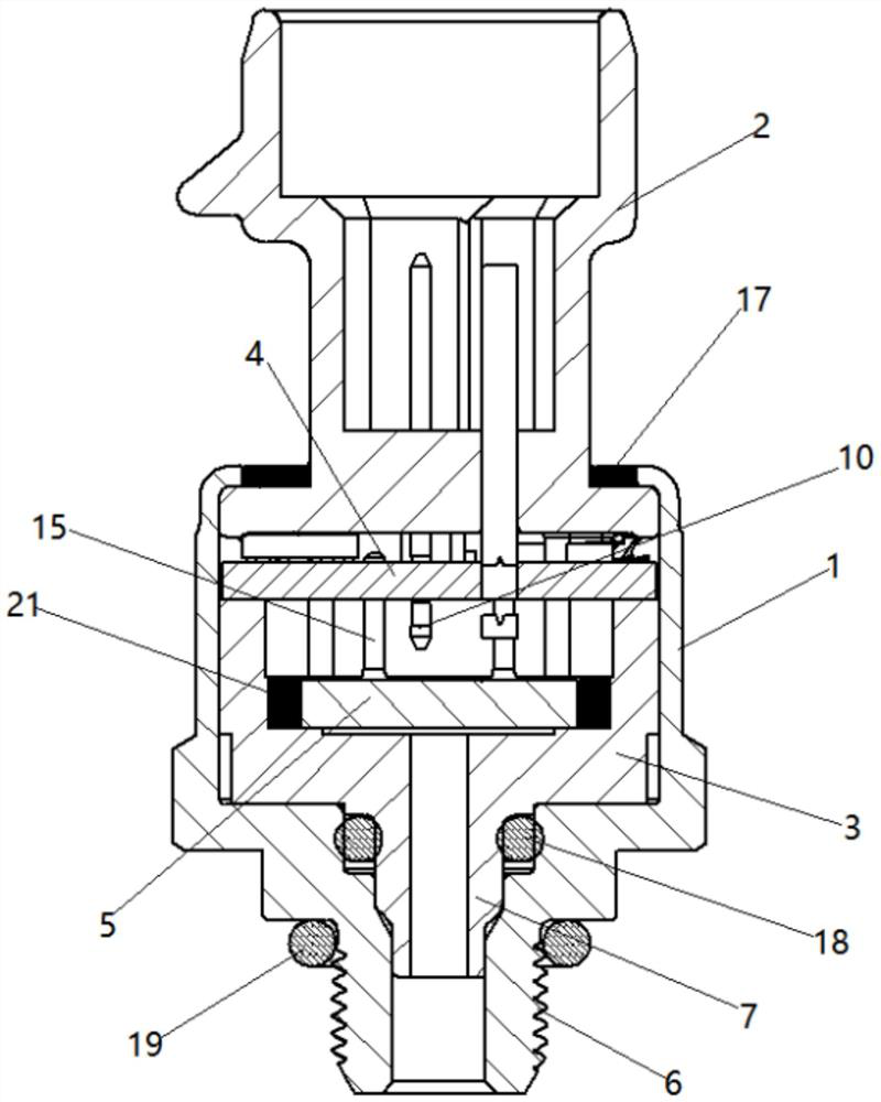
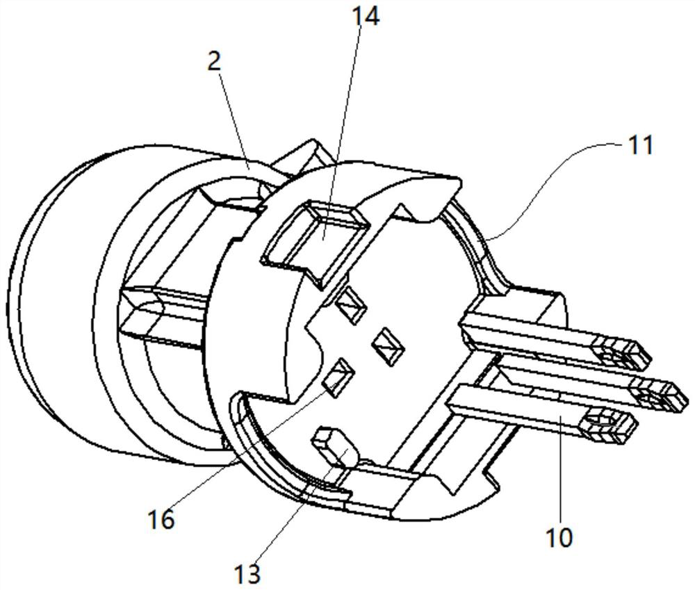
[0026] Such as Figure 1-6 As shown, the present invention provides a pressure sensor based on ceramic resistance sensing technology, including a sensor housing 1, an electrical connector 2, a sensitive element seat 3, a PCB circuit board 4, and a pressure sensitive element 5, and the lower end of the sensor housing 1 is integrated The threaded pipe joint 6 is formed, and the sensor housing 1 is connected with the installation hole on the pipeline or the cavity wall through the threaded pipe joint 6 at the low...


PUM


Abstract

The invention discloses a pressure sensor based on a ceramic resistance sensing technology, which comprises a sensor shell, an electrical connector, a sensitive element seat, a PCB (Printed Circuit Board) and a pressure sensitive element, a threaded pipe joint is integrally formed at the lower end of the sensor shell, and the sensitive element seat is arranged in an inner cavity of the sensor shell; a fluid pipeline inserted into an inner cavity of the threaded pipe joint is integrally arranged at the lower end of the sensitive element seat, a square concave cavity is formed in the upper end face of the sensitive element seat, the pressure sensitive element is installed in the square concave cavity, the lower end of the electrical connector is arranged in the sensor shell, and three PI N needles are vertically inserted into the inner end face of the electrical connector. The PCB is clamped into two sets of U-shaped grooves symmetrically formed in the outer side wall of the lower end of the electrical connector, three sets of connecting holes connected with the lower ends of the three PI N pins respectively are formed in the PCB, the lower end face of the PCB abuts against the top face of the supporting boss, and the PCB is connected with the pressure sensitive element through four sets of pin tin soldering. According to the invention, high-precision detection can be realized, and the structural stability is high.

Description

technical field [0001] The invention relates to a pressure sensor technology, in particular to a pressure sensor based on ceramic resistance sensing technology. Background technique [0002] Pressure sensors are mainly used to collect the pressure of liquid or gas in the cavity or pipeline. With the continuous improvement of control technology and control system, the traditional control method is no longer suitable for the needs of the industry, and the adaptability of the traditional sensor accuracy also needs to be further improved. For example, in the automobile air-conditioning industry, traditional automobiles use pressure switches to determine the operation or stop of the system by collecting a certain pressure value of the refrigerant in the pipeline. This simple and crude control method is not only inefficient, but also wastes energy and is easy to damage the system. Replaced by a pressure sensor. In addition, traditional pressure sensors based on MEMS and ceramic ...

Claims


Application Information

Patent Timeline
Patent Type & Authority Applications(China)
IPC IPC(8): G01L9/02G01L19/00G01L19/06G01L19/14
CPCG01L9/02G01L19/0061G01L19/148G01L19/149G01L19/0672
Inventor 罗逸民安吉洛·利奥李克彬
Owner 布瑞特智联科技(杭州)有限公司
Why Eureka
Try Eureka