Hybrid Excitation Turbo Generator with Multi-stage Axial-Centrifugal Ventilation and Cooling System

A turbo-generator, ventilation and cooling technology, applied in cooling/ventilation devices, magnetic circuits characterized by magnetic materials, magnetic circuits, etc., can solve the problem of increasing the cooling gas flow and pressure in the turbo-generator, reducing The volume of the turbo-generator, the temperature of the rotor excitation winding and the end member are high, so as to achieve the effect of increasing the flow rate and pressure, enhancing the strength of the air gap magnetic field, and increasing the power density

Active Publication Date: 2022-06-07
HARBIN UNIV OF SCI & TECH +2
View PDF15 Cites 0 Cited by
  • Summary
  • Abstract
  • Description
  • Claims
  • Application Information

AI Technical Summary

Problems solved by technology

[0004] The purpose of the present invention is to provide a hybrid excitation turbogenerator with a multi-stage axial flow-centrifugal ventilation and cooling system to solve the problems caused by the low power density of the traditional turbogenerator and the unreasonable ventilation design of the stator area and the rotor area. Iron core, stator winding, rotor core, rotor excitation winding and end components are overheated, which significantly improves the power density of the turbogenerator and reduces the volume of the turbogenerator. Through multi-stage axial flow - The design of the centrifugal ventilation cooling system can effectively improve the utilization rate of cooling gas, increase the flow and pressure of cooling gas in the turbogenerator, reduce the temperature of each component and the temperature difference in the axial direction, and improve the power generation of the turbogenerator. Ability to operate safely and stably

Method used


Image

  • Hybrid Excitation Turbo Generator with Multi-stage Axial-Centrifugal Ventilation and Cooling System
  • Hybrid Excitation Turbo Generator with Multi-stage Axial-Centrifugal Ventilation and Cooling System
  • Hybrid Excitation Turbo Generator with Multi-stage Axial-Centrifugal Ventilation and Cooling System

Examples


specific Embodiment approach 1

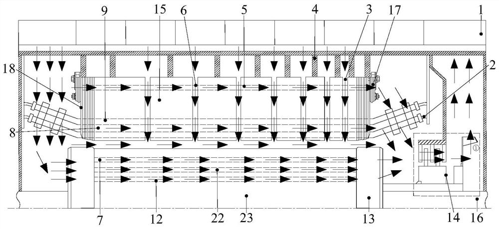
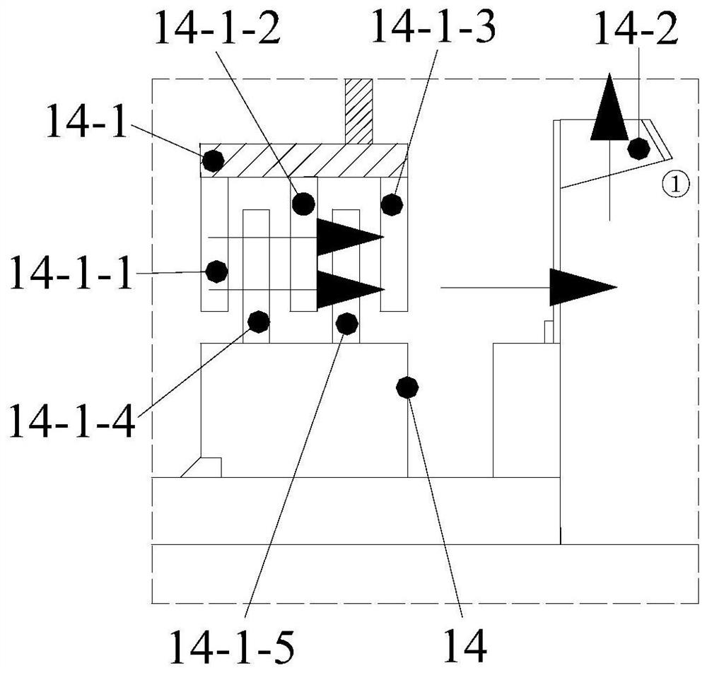
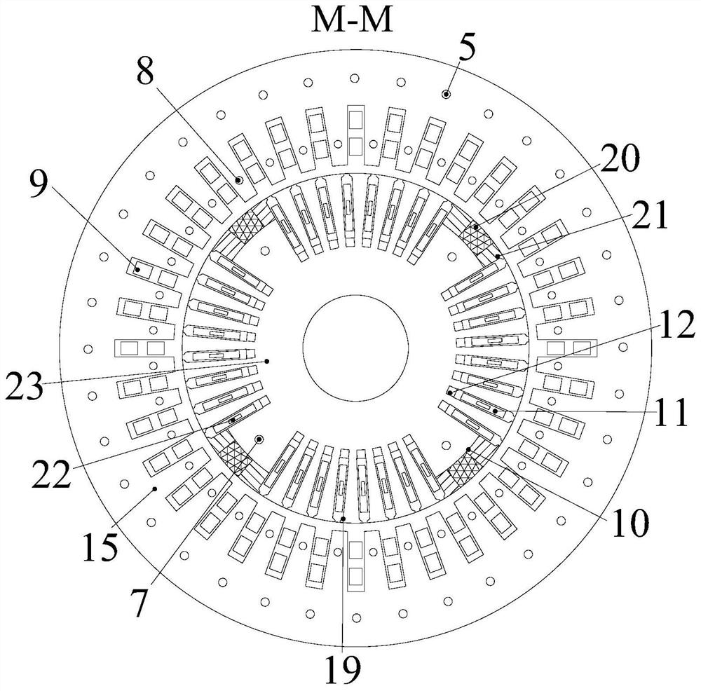
[0020] Embodiment 1: Combining figure 1 , figure 2 , image 3Illustrating this embodiment, it includes a cooler 1, a water pipe 2, a radial ventilation channel 3, a stator bracket 4, a stator yoke axial ventilation hole 5, an air guide ring 6, a rotor core axial ventilation hole 7, and a stator tooth portion. Axial ventilation hole 8, stator winding 9, sector groove 10, rotor excitation winding 11, rotor slot bottom ventilation channel 12, rotor guard ring 13, multi-stage axial-centrifugal hybrid fan 14, stator core segment 15, rotating shaft 16. Magnetic shield 17, pressure finger 18, rectangular deep groove 19, high coercivity permanent magnet 20, low coercivity permanent magnet 21, rotor inner cooling air passage 22 and rotor iron core 23, multi-stage axial flow-centrifugal The hybrid multi-stage fan 14 is composed of a multi-stage axial fan 14-1 and a centrifugal fan 14-2; the multi-stage axial fan 14-1 is composed of a first-stage static fan 14-1-1, a second-stage The...

specific Embodiment approach 2

[0023] Specific implementation mode 2: Combining Figure 4 Describing this embodiment, the difference between this embodiment and the first embodiment is that the cross-sectional area of ​​the axial ventilation hole 5 in the stator yoke portion gradually decreases along the direction of the cooling gas flow, so that the cooling gas velocity is along the direction of the cooling gas flow. Gradually increases, thereby reducing the influence of the cooling effect of the yoke of the stator core segment 15 becoming worse due to the increase in the temperature of the cooling gas, improving the utilization rate of the cooling gas, and further reducing the temperature of the yoke of the stator core segment 15 . Other components and connection relationships are the same as those in the first embodiment.

specific Embodiment approach 3

[0024] Specific implementation three: combination Figure 5 Describing this embodiment, the difference between this embodiment and the first embodiment is that the cross section of the axial ventilation holes 8 of the stator teeth is changed from a circle to a rectangle, which improves the surface heat dissipation coefficient of the stator core segment 15 and further reduces the The temperature of the teeth of the stator core segment 15 of equal thickness. Other components and connection relationships are the same as those in the first embodiment.


PUM


Abstract

The invention discloses a hybrid excitation turbogenerator with a multistage axial flow-centrifugal ventilation and cooling system, which relates to the field of motors. In order to solve the problems of low power density and high component temperature of the existing turbogenerators, the present invention installs stator core sections with different thicknesses along the axial direction, and radial ventilation grooves are left between the stator core sections. There are axial ventilation holes on the stator yoke and axial ventilation holes on the stator teeth. The multi-stage axial flow-centrifugal hybrid fan is installed on one side of the turbogenerator. The outer surface of the rotor core is provided with fan-shaped grooves and rectangular deep holes. Slots, high-coercivity permanent magnets and low-coercivity permanent magnets are installed in fan-shaped grooves, rotor excitation windings are installed in rectangular deep grooves, rotor internal cooling ventilation channels are opened in rotor excitation windings, and rotor excitation windings are opened below There is a ventilation channel at the bottom of the rotor groove, and an axial ventilation hole of the rotor core is opened under the fan-shaped groove. The invention improves the power density and cooling effect of the generator, has a simple structure and is easy to realize.

Description

Technical field: [0001] The invention relates to a hybrid excitation steam turbine generator with a multi-stage axial flow-centrifugal ventilation cooling system, belonging to the field of electric motors. Background technique: [0002] With the rapid development of the national economy, electric energy has become one of the important power sources and material foundations necessary for social development and residents' life. The capacity of the turbo-generator, the core equipment in a large-scale power station, is relatively large. The traditional turbo-generator only uses the excitation winding to apply the excitation current to generate the magnetic field in the generator, which leads to the low power density of the turbo-generator and the The axial length of the turbogenerator is long, and the temperature difference in the axial direction will lead to large thermal stress and thermal deformation of the stator winding in the axial direction, which directly affects the ser...

Claims


Application Information

Patent Timeline
Patent Type & Authority Patents(China)
IPC IPC(8): H02K9/10H02K1/20H02K1/12H02K1/2706H02K1/274H02K1/276H02K1/32H02K1/02
CPCH02K9/10H02K1/20H02K1/12H02K1/32H02K1/223H02K1/2706H02K1/02H02K2213/03Y02E20/14
Inventor 韩继超董桀辰刘玉飞孙玉田郑萍张春莉王洋王超戈宝军陶大军
Owner HARBIN UNIV OF SCI & TECH
Why Eureka
Try Eureka