Anti-sticking device for electromechanical actuator and sticking fault judgment method

An electromechanical actuator and anti-jamming technology, which is applied to electromechanical devices, transmission control, electric components, etc. Eliminate problems such as hydraulic links to avoid stalling, improve practicability, and ensure stability

Active Publication Date: 2021-09-07
BEIHANG UNIV
View PDF7 Cites 1 Cited by
  • Summary
  • Abstract
  • Description
  • Claims
  • Application Information

AI Technical Summary

Problems solved by technology

The fault isolation mechanism in the above-mentioned patent has the following deficiencies: although it has a certain protection function, it cannot judge the stuck situation in time, and cannot provide effective instructions to the motor in the actuator; The actuator cancels the purpose of the hydraulic link, so it needs to be improved

Method used


Image

  • Anti-sticking device for electromechanical actuator and sticking fault judgment method
  • Anti-sticking device for electromechanical actuator and sticking fault judgment method
  • Anti-sticking device for electromechanical actuator and sticking fault judgment method

Examples


Embodiment 1

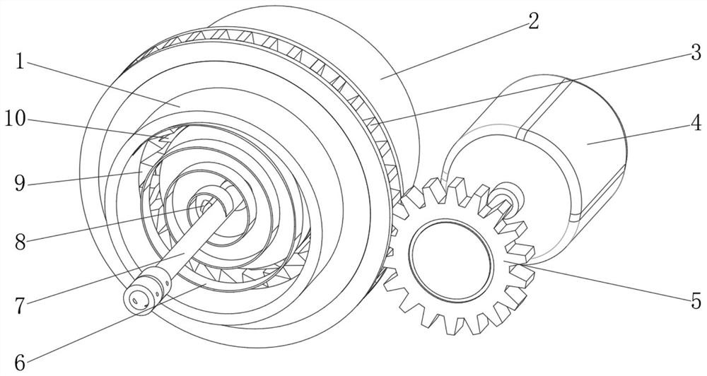
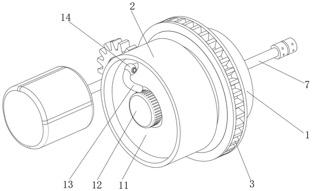
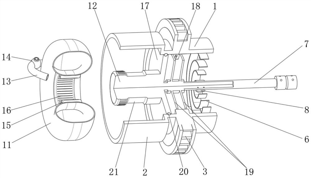
[0043] An anti-seize device for an electromechanical actuator, such as Figure 1-4 As shown, it includes a housing 1, a driven gear 3, a driving gear 5 and a driven shaft 7, the driven gear 3 is integrally arranged on the outer wall of the housing 1, the driven gear 3 is meshed with the driving motor 4, and the housing One side of the body 1 is provided with a drive motor 4 that drives the drive gear 5 to rotate, and the drive gear 5 is rotatably connected to the output end of the drive motor 4. The inner side of the housing 1 is provided with a linkage part 10, and the outer wall of the driven shaft 7 is Two mounting discs 19 are welded, the linkage part 10 includes a ratchet 18 and a ratchet spring 23, the ratchet 18 is installed between the two mounting discs 19 through a connecting shaft 24, and the ratchet 18 is rotatably connected to the outer wall of the connecting shaft 24, so The inner wall of the casing 1 is integrally provided with evenly distributed inner teeth 9, ...

Embodiment 2

[0050] An anti-seize device for an electromechanical actuator, such as Figure 5-7 As shown, in order to improve the detection speed; this embodiment makes the following improvements on the basis of Embodiment 1: the planar scroll spring 6 is replaced by a shrapnel 25, and the two ends of the shrapnel 25 are respectively fixed on the inner wall of the housing 1 and from the On the outer peripheral wall of the driven shaft 7, each shrapnel 25 constitutes a tornado-like structure, and the pressure sensor 8 is installed on the outer peripheral wall of the driven shaft 7 through a fixed bracket 26; , through the rapid deformation of the shrapnel 25 to contact the pressure sensor 8, so that the pressure sensor 8 can sense the stuck phenomenon faster, which is beneficial to control the drive motor 4 to stop working in time, and improves the reliability.

[0051] In order to improve reliability, such as Figure 6 , Figure 7 As shown, the first annular airbag 11 is replaced with a ...

Embodiment 3

[0053] An anti-seize device for an electromechanical actuator, such as Figure 8 As shown, in order to simplify the structure; this embodiment makes the following improvements on the basis of Embodiment 1: the second annular air bag 27 is replaced by an elastic bag 31, and the elastic bag 31 is bonded to the circumferential inner wall of the annular seat 2, The inner wall of the elastic bag 31 is integrally provided with evenly distributed second arc-shaped protrusions 32, the second arc-shaped protrusions 32 are adapted to the arc-shaped grooves 29, and the second arc-shaped protrusions 32 are provided with Evenly distributed air holes 30; by setting the elastic bag 31 and the second arc-shaped protrusion 32, the elastic force of the elastic bag 31 can be used to maintain the firmness of contact with the friction column 12. When the driven shaft 7 is stuck, the second arc The shape protrusion 32 deforms and breaks away from the arc-shaped groove 29, so that airflow is generat...


PUM


Abstract

The invention discloses an anti-sticking device for an electromechanical actuator and a sticking fault judgment method, relates to the technical field of sticking fault isolation devices, and aims to better judge the sticking phenomenon. The device comprises a shell, driven teeth, a drive gear and a driven shaft, wherein the driven teeth are integrally arranged on the circumferential outer wall of the shell, and the driven teeth are meshed with a driving motor. The method comprises the following steps that the driving motor works to drive the drive gear to rotate, and then the shell is driven to rotate through the driven gear. When the driven shaft with the load is stuck, rotation of a pawl is blocked, and a ratchet spring enables the pawl to slide on inner teeth in a deformation mode, so that the shell can continue to rotate, and the locked-rotor phenomenon of the driving motor is avoided; and in addition, along with the fact that the driven shaft is stuck and the shell rotates, a spiral spring can be gradually tightened on the driven shaft, a pressure sensor is extruded, a signal of the pressure sensor is transmitted to an external control unit, and the control unit controls the driving motor to stop working.

Description

technical field [0001] The invention relates to the technical field of stuck fault isolation devices, in particular to an electromechanical actuator stuck preventing device and a stuck fault judging method. Background technique [0002] As one of the main driving components of the aircraft steering gear system, the electromechanical actuator is widely used on various rudder surfaces. During the operation of the electromechanical actuator, it needs to drive the load to work according to the set method. In some cases, if it is disturbed by the outside At this time, the transmission of the electromechanical actuator may be stuck, which may cause the output end of the electromechanical actuator to be blocked. If there is no protection mechanism for protection, the motor will be burned if it is blocked for a long time; in addition, the electromechanical actuator After being stuck, it may cause the rudder surface of the aircraft to be stuck, thereby causing serious casualties, so ...

Claims


Application Information

Patent Timeline
Patent Type & Authority Applications(China)
IPC IPC(8): F16D41/12F16D63/00F16D65/78F16D67/02F16H61/12H02K7/116H02K11/20
CPCF16D41/12F16D63/006F16D67/02F16D65/78F16H61/12H02K7/116H02K11/20F16H2061/1208
Inventor 付永领李林杰朱德明王明康
Owner BEIHANG UNIV
Why Eureka
Try Eureka