
Hydrogen concentration monitoring device, system and method

A concentration monitoring and hydrogen technology, applied in measurement devices, sampling devices, thermal conductivity of materials, etc., can solve the problems of requiring a long time, long response time to start, difficult to adapt to hydrogen concentration detection, etc., and achieve the effect of improving the response time.

Pending Publication Date: 2021-09-07
CHINA NUCLEAR POWER ENG CO LTD
View PDF12 Cites 1 Cited by
  • Summary
  • Abstract
  • Description
  • Claims
  • Application Information

AI Technical Summary

Problems solved by technology

[0003] CN205003131U discloses a kind of integrated hydrogen concentration monitoring device, the sample gas in the storage tank with micro-negative pressure environment is pumped into the hydrogen analyzer for analysis through the compressed air ejector, considering the radiation safety problem, the hydrogen concentration monitoring device and The storage tanks are often far apart, and the flow rate required by the hydrogen analyzer is small, which leads to a long time for the compressed air injector to pump out the original gas in the delivery pipeline when the device is started, which leads to the start-up response of the device The time is too long, it is difficult to adapt to the detection of hydrogen concentration in emergency situations

Method used


Image

  • Hydrogen concentration monitoring device, system and method
  • Hydrogen concentration monitoring device, system and method
  • Hydrogen concentration monitoring device, system and method

Examples


Embodiment 1

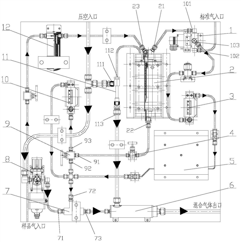
[0054] Such as figure 1 As shown, the hydrogen concentration monitoring device of this embodiment includes: a negative pressure suction assembly, a vortex condenser and a thermal conductivity sensor 5;

[0055] The vortex condenser has a first sample gas outlet 21 and a second sample gas outlet 22, the first sample gas outlet 21 is connected to the inlet of the thermal conductivity sensor 5,

[0056] The negative pressure suction assembly includes a compressed air injector 7, which is connected to the second sample gas outlet 22, and is used to generate a low pressure to draw the sample gas in the sample gas source into the vortex condenser, and the compressed air injector 7 is also connected with the outlet of thermal conductivity sensor 5,

[0057] The vortex condenser is used to condense the sample gas entering the vortex condenser to remove the water vapor in the sample gas,

[0058] Part of the condensed sample gas enters the compressed air injector 7 through the second...

Embodiment 2

[0107] Such as figure 2 As shown, the present embodiment provides a hydrogen concentration monitoring system, including a signal processing device and the hydrogen concentration monitoring device of Embodiment 1, and the signal processing device is electrically connected to the thermal conductivity sensor 5 of the hydrogen concentration monitoring device for collecting heat The hydrogen concentration detection electrical signal output by the conductive sensor 5 is converted and processed to output the concentration value of hydrogen in the sample gas.

[0108] Specifically, the hydrogen concentration detection electrical signal output by the thermal conductivity sensor 5 is a weak electrical signal, and the signal processing device converts the weak electrical signal into a standard concentration signal to obtain the hydrogen concentration in the sample gas. At the same time, the signal processing device also realizes the calibration work of the sensor remotely.

[0109] The...

Embodiment 3

[0112] This embodiment provides a method for monitoring hydrogen concentration using the hydrogen concentration monitoring system of Embodiment 2, comprising the following steps:

[0113] Including system debugging and system running two processes. For specific gas flow direction, see figure 1 , where the large light-colored arrows indicate the flow direction of compressed air, the small arrows indicate the flow direction of sample gas, and the large dark-colored arrows indicate the flow direction of mixed gas.

[0114] S1: System debugging:

[0115] S1.1: Switch the second three-way valve 1 (three-way solenoid valve), so that its second air inlet is connected with its air outlet, and the standard gas source passes standard gas into the thermal conductivity sensor 5 to control the heat. After calibration, switch the second three-way valve 1 so that its first air inlet is connected with its air outlet;

[0116] S1.2: Open the external compressed air inlet valve, and open the...


PUM

PropertyMeasurementUnit
Thicknessaaaaaaaaaa

Abstract

The invention provides a hydrogen concentration monitoring device, system and method. The device comprises a compressed air ejector, a vortex condenser and a thermal conductivity type sensor, the compressed air ejector is used for generating low pressure so as to suck sample gas in the sample gas source into the vortex condenser, the vortex condenser is used for condensing the sample gas entering the vortex condenser so as to remove water vapor in the sample gas, one part of the condensed sample gas enters the compressed air ejector through a second sample gas outlet and then is discharged, the other part of the condensed sample gas enters the thermal conductivity type sensor from the first sample gas outlet, then enters the compressed air ejector through the outlet of the thermal conductivity type sensor and is discharged, and the thermal conductivity type sensor is used for detecting the concentration of hydrogen in the sample gas entering the thermal conductivity type sensor. The vortex condenser is used for condensing and shunting the sample gas, so that when the device is started, the compressed air ejector can extract the sample gas in the sample gas source with relatively large airflow so as to extract the original gas in the conveying pipeline in a relatively short time, and the response time of the device is prolonged.

Description

technical field [0001] The invention specifically relates to a hydrogen concentration monitoring device, system and method. Background technique [0002] In the nuclear fuel reprocessing project, the highly radioactive waste liquid in some storage tanks will produce hydrogen gas due to radiolysis, and its concentration will gradually accumulate over time. The accumulation of hydrogen gas reaches the upper limit of the explosion limit of hydrogen gas, and there is a risk of explosion. Therefore, it is necessary to install a hydrogen concentration monitoring device, which can monitor the hydrogen release concentration of the highly radioactive waste liquid in real time, so that the exhaust system can discharge the gas in the gas phase. [0003] CN205003131U discloses a kind of integrated hydrogen concentration monitoring device, the sample gas in the storage tank with micro-negative pressure environment is pumped into the hydrogen analyzer for analysis through the compressed a...

Claims


Application Information

Patent Timeline
IPC IPC(8): G01N25/18G01N1/24G01N1/34G01N1/40G01N1/42
CPCG01N25/18G01N1/24G01N1/34G01N1/4077G01N1/42G01N2001/4088Y02E30/30
Inventor 马世海张博李晓薇冯存强刘晓莉崔国华唐翊桐李睿冯炜崔瑶杨颖策张浩王宇婷刘思源贾敏松金珊朱世钊邹洪伶周楠
Owner CHINA NUCLEAR POWER ENG CO LTD
Learn More