
A chip resistor precision engraving machine

A chip resistor and precision engraving technology, which is applied in the direction of resistors, resistor manufacturing, and resistor manufacturing through photolithography, etc., can solve the problem that the resistance adjustment accuracy and resistance adjustment pass rate of chip resistors are greatly affected, and the manual grinding work is hard , uneven grinding and other problems, to achieve the effect of improving, reducing manpower consumption, and stabilizing quality

Active Publication Date: 2022-06-28
湖南旺诠电子科技有限公司
View PDF7 Cites 0 Cited by
  • Summary
  • Abstract
  • Description
  • Claims
  • Application Information

AI Technical Summary

Problems solved by technology

However, through this processing method, there are manual grinding work and low efficiency. At the same time, due to uneven grinding, the resistance adjustment accuracy and resistance adjustment pass rate of chip resistors are easily affected by human factors.

Method used


Image

  • A chip resistor precision engraving machine
  • A chip resistor precision engraving machine
  • A chip resistor precision engraving machine

Examples


Embodiment

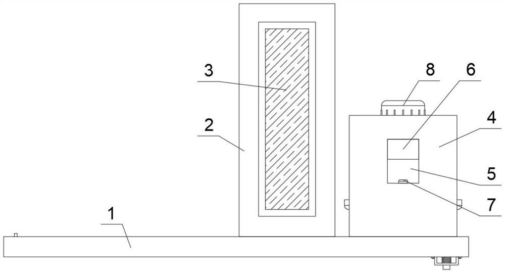
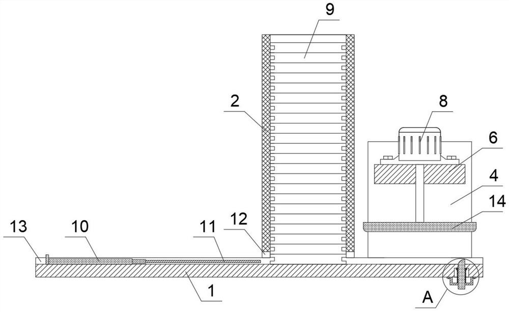
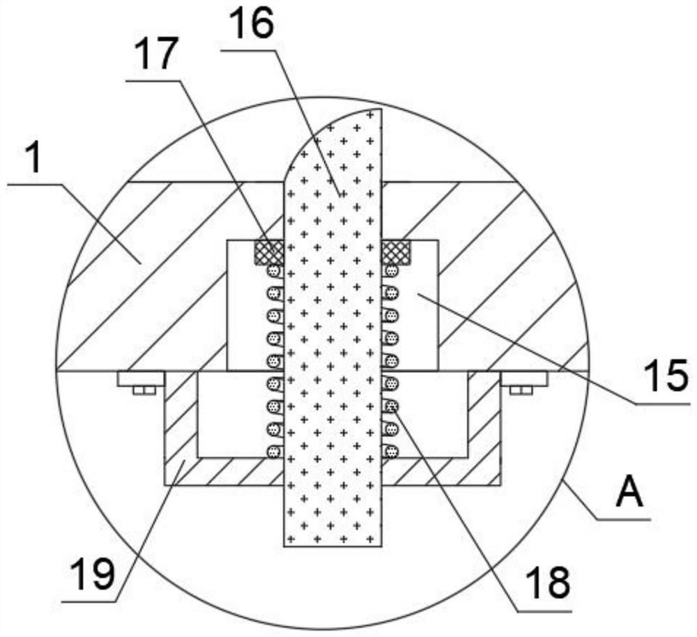
[0034] example, see Figure 1-5, the present invention provides a technical solution: a chip resistor precision engraving machine, comprising a track base plate 1, the inside of the track base plate 1 has a track chute 13, and the top of the track base plate 1 is fixedly connected with two parallel track support plates 4. A gravity slide plate 6 is slidably connected between the two track support plates 4. The inside of the track support plate 4 has a slide plate slot 5 for the gravity slide plate 6 to slide, and a trigger switch 7 is installed at the inner bottom of the slide plate slot 5. A drive motor 8 is installed on the top, and a chip resistance grinding disc 14 is fixedly connected to the bottom of the output shaft of the drive motor 8. The bottom of the outer end face of the chip resistance grinding disc 14 is provided with rounded corners, and the top of the track base plate 1 is fixedly connected with a top and a The material storage box 2 with the bottom opening st...


PUM


Abstract

The invention discloses a precision engraving machine for patch resistors, which comprises a track bottom plate, a track chute inside the track bottom plate, two track support plates distributed in parallel fixedly connected to the top of the track bottom plate, the two track Gravity slides are slidably connected between the support plates, and the inside of the track support plate has a slide plate groove for the slide of the gravity slide plate, a trigger switch is installed on the inner bottom of the slide plate groove, and a drive motor is installed on the top of the gravity slide plate. The bottom of the output shaft of the drive motor is fixedly connected with a chip resistor grinding disc, and the bottom of the outer end surface of the chip resistor grinding disc is provided with rounded corners. In the present invention, firstly, through the automatic grinding structure, the consumption of manpower is reduced, and the effect of grinding is improved; secondly, the feeding of chip resistors is realized while discharging, thereby improving the processing efficiency. Finally, a stable conveying mechanism is adopted to improve the effect of grinding chip resistors.

Description

technical field [0001] The invention relates to the technical field of chip resistance processing devices, in particular to a chip resistance precision engraving machine. Background technique [0002] Chip resistors are also business card-type fixed resistors, which are one of the metal glass glaze resistors. It is a resistor made by mixing metal powder and glass glaze powder and printing it on the substrate by screen printing. Resistant to humidity and high temperature, with a small temperature coefficient. It can greatly save the cost of circuit space and make the design more refined. SMD components have the advantages of small size, light weight, high installation density, strong shock resistance, strong anti-interference ability, good high frequency characteristics, etc., with small size, light weight, suitable for reflow soldering and wave soldering, stable electrical performance, reliable High performance, low assembly cost, matching with automatic placement equipme...

Claims


Application Information

Patent Timeline
Patent Type & Authority Patents(China)
IPC IPC(8): H01C17/00
CPCH01C17/003H01C17/00
Inventor 孙永光
Owner 湖南旺诠电子科技有限公司
Learn More