Comprehensive energy utilization system

A technology that integrates energy and subsystems, applied in the field of power generation, and can solve the problems affecting the stable operation of the municipal power grid and the impact of the municipal power grid.

Pending Publication Date: 2021-09-07
CGN WIND ENERGY +1
View PDF6 Cites 4 Cited by
  • Summary
  • Abstract
  • Description
  • Claims
  • Application Information

AI Technical Summary

Problems solved by technology

[0004] In view of the related technologies mentioned above, the inventor believes that energy sources such as wind power and solar energy have random fluctuations, and the corresponding electric energy also fluctuates randomly; it

Method used


Image

  • Comprehensive energy utilization system
  • Comprehensive energy utilization system
  • Comprehensive energy utilization system

Examples


Embodiment 1

[0057] The embodiment of the present application discloses a comprehensive energy utilization system.

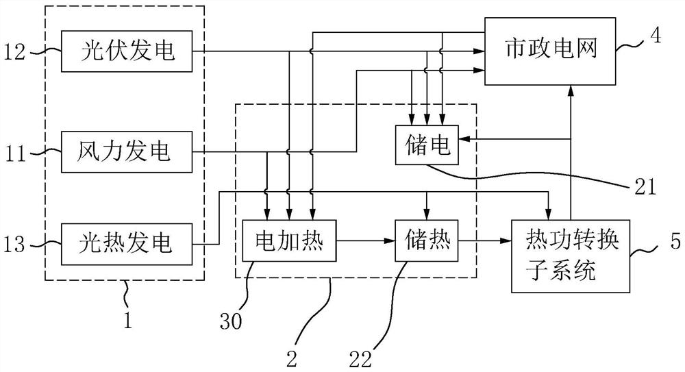
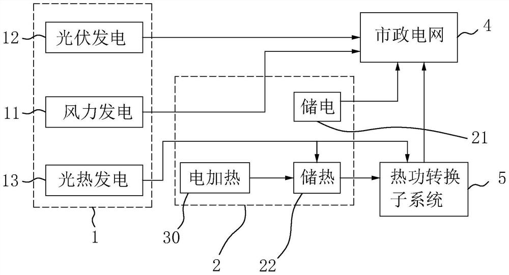
[0058] refer to figure 1 , a comprehensive energy utilization system, including a power generation subsystem 1 , an energy storage subsystem 2 and a thermal power conversion subsystem 5 .

[0059] The power generation subsystem 1 is used to generate electric energy from energy sources and incorporate the electric energy into the municipal power grid 4; the energy storage subsystem 2 is respectively connected to the power generation subsystem 1 and the municipal power grid 4; the thermal power conversion subsystem 5 is respectively connected to the energy storage subsystem 2 and municipal power grid 4.

[0060] During the low power consumption period, the energy storage subsystem 2 can directly or indirectly store the excess electric energy of the power generation subsystem 1 and the municipal power grid 4 to reduce power abandonment; it can also directly convert the excess ...

Embodiment 2

[0083] The embodiment of the present application discloses a comprehensive energy utilization system.

[0084] Based on embodiment 1, the difference between the embodiment of the present application and embodiment 1 is:

[0085] refer to Figure 6 , the energy storage subsystem 2 includes an electric motor 23 , an air compressor 24 , a cooler 25 , a pressure energy storage container 26 , a regenerator 27 , a turbine 28 and an air compressor generator 29 .

[0086] The motor 23 is used to convert electric energy into kinetic energy for driving the air compressor 24 to run; the air compressor 24 uses the kinetic energy generated by the motor 23 to compress the air; the cooler 25 is used to cool the air before entering the pressure energy storage container 26 , to reduce the loss of air in the pressure energy storage container 26; the regenerator 27 is used to heat the air and drive the turbine 28 to run; the turbine 28 is used to decompress the air output from the pressure ener...

Embodiment 3

[0092] The embodiment of the present application discloses a comprehensive energy utilization system.

[0093] Based on Embodiment 1 or Embodiment 2, the comprehensive energy utilization system also includes a power load monitoring subsystem and a central control subsystem; through the short-term power consumption forecast on the power load side, the prediction of power consumption on the power load side can be improved. It is convenient to realize the control of the power generation subsystem 1 and the energy storage subsystem 2, and improve the stability of the power generation subsystem 1, the energy storage subsystem 2, and the municipal power grid 4.

[0094] The electricity load monitoring subsystem is used to predict the electricity demand on the electricity load side. Specific forecasting methods include:

[0095]S100: Divide the power consumption side into several power consumption unit areas.

[0096] Specifically, the division rules can be planned according to adm...


PUM


Abstract

The invention relates to the technical field of power generation, in particular to a comprehensive energy utilization system. The comprehensive energy utilization system comprehensively utilizes various energy sources to generate electric energy, so the power supply stability of a power supply side is improved, abandoned power is reduced, gradient utilization of the energy sources is realized, and the utilization efficiency of the energy sources is improved. And through short-term electricity consumption prediction on the electricity consumption load side, judgment and control on electricity consumption of the electricity consumption load side can be improved, and the stability of electric networks such as a power generation subsystem, an energy storage subsystem and a municipal power grid can be improved.

Description

technical field [0001] The present application relates to the technical field of power generation, in particular to an integrated energy utilization system. Background technique [0002] The use of renewable energy such as solar energy, wind power, and tides to generate electricity can save a large number of non-renewable fossil resources. As the construction of various renewable energy power stations increases, the amount of electricity generated by renewable energy power stations that are integrated into the grid continues to grow. [0003] Due to the uneven distribution of natural resources, renewable energy power stations are mostly far away from the load area. Therefore, it is necessary to carry out large-scale power transmission through power transmission technologies such as high-voltage transmission technology or direct current transmission technology. [0004] In view of the related technologies mentioned above, the inventor believes that energy sources such as wi...

Claims


Application Information

Patent Timeline
IPC IPC(8): H02J3/38H02J3/28H02J3/30H02J3/32H02J3/46H02J3/14
CPCH02J3/381H02J3/28H02J3/30H02J3/32H02J3/466H02J3/144H02J3/003H02J2203/20H02J2300/24H02J2300/28H02J2300/40Y04S20/222Y02E60/16Y02E70/30Y02B70/3225Y02E10/56
Inventor 张亚南汤建方唐宪友许程
Owner CGN WIND ENERGY
Why Eureka
Try Eureka