
Filter device

A filtering device and waveguide technology, applied in waveguides, waveguide devices, resonators, etc.

Inactive Publication Date: 2021-09-07
THE FUJIKURA CABLE WORKS LTD
View PDF6 Cites 0 Cited by
  • Summary
  • Abstract
  • Description
  • Claims
  • Application Information

AI Technical Summary

Problems solved by technology

Therefore, it is not possible to incorporate a movable mechanism for changing the passband as described in Patent Document 1 inside the waveguide region.

Method used


Image

  • Filter device
  • Filter device
  • Filter device

Examples


Embodiment Construction

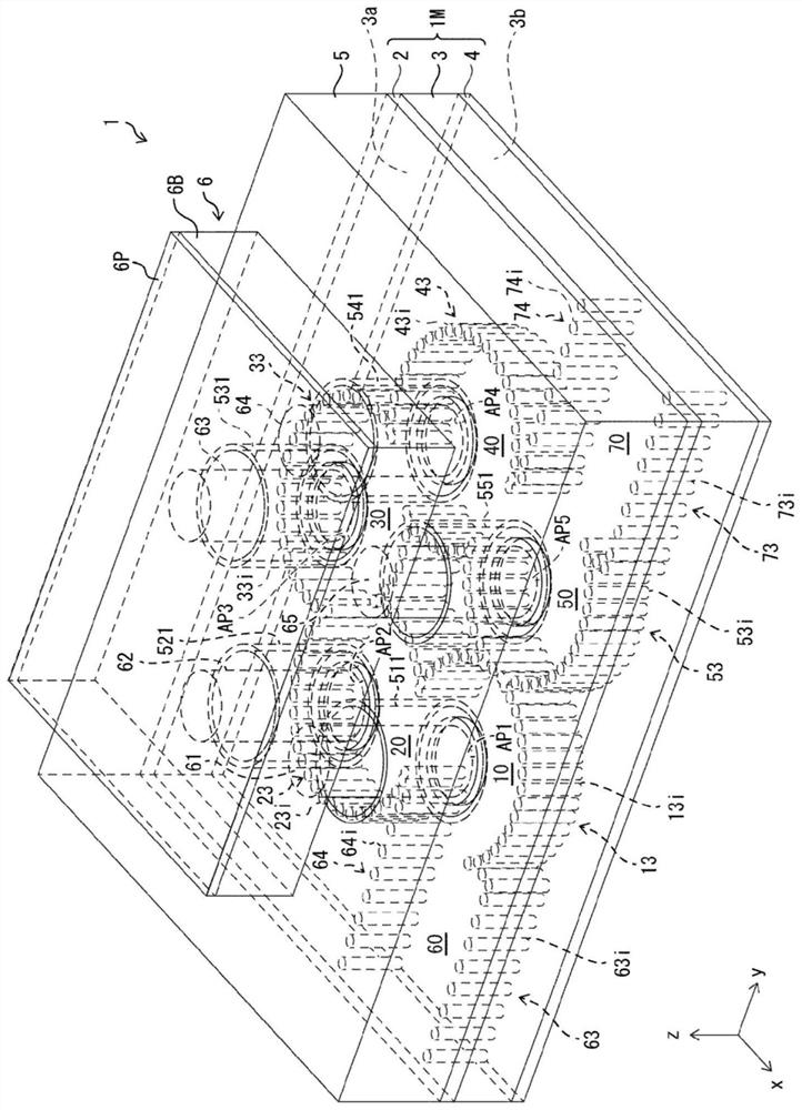
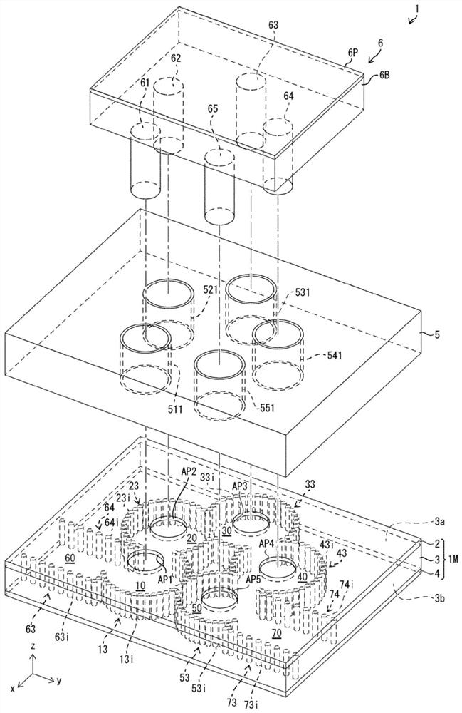
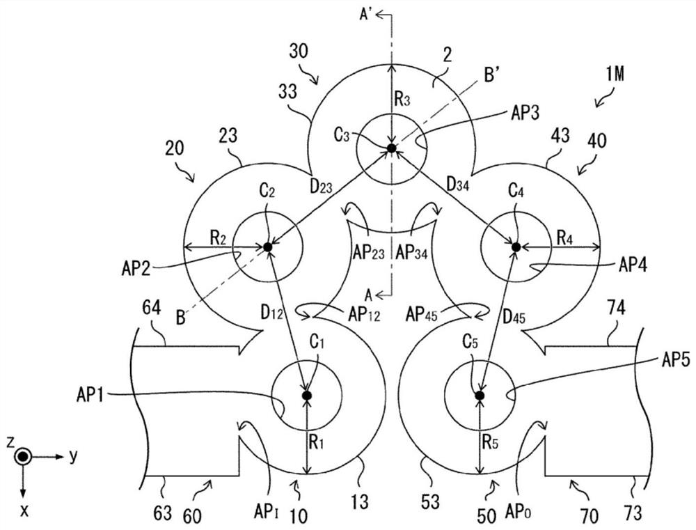
[0018] refer to Figure 1 to Figure 4 , the filter device 1 according to one embodiment of the present invention will be described. figure 1 is a perspective view of the filter device 1 . figure 2 It is an exploded perspective view of the filter device 1 . image 3 It is a plan view schematically showing the outline of the five resonators 10 to 50 constituting the filter device 1 . In addition, in image 3 In , the column walls 13 , 23 , 33 , 43 , 53 , 63 , 64 , 73 , and 74 constituted by conductor column groups are shown as virtual continuous conductor walls. Figure 4 yes image 3 A cross-sectional view of resonator 30 is shown, and is image 3 Sectional view in line AA' shown.

[0019] Such as figure 1 and figure 2 As shown, the filter device 1 includes a filter main body 1M, a block 5 , and a rod control unit 6 . In addition, the filter main body 1M includes a conductor layer 2 , a dielectric substrate 3 , a conductor layer 4 , and pillar walls 13 , 23 , 33 , 43...


PUM


Abstract

The present invention provides a filter device that comprises a post wall waveguide, and for which the pass band is variable. This filter device (1) comprises a post wall waveguide (filter body 1M) that functions as a plurality of resonators (10-50); cavities (tubes 551-555) that are joined with each resonator (10-50) with apertures (AP1-AP5) formed on a wide wall (conductor layer 2) interposed therebetween; rods (61-65) inserted in the cavities (tubes 551-555); and a rod control mechanism (piezoelectric element 6P) that controls the position of the rods (61-65).

Description

technical field [0001] The invention relates to a variable filter device with a cylindrical wall waveguide and a variable passband. Background technique [0002] Patent Document 1 describes a filter device that makes a part of the centimeter wave band a passband and can change the passband. In addition, this filtering device is referred to as a tunable filter in Patent Document 1. The filtering device adopts a hollow waveguide as a waveguide for guiding centimeter waves, and a movable mechanism for changing the passband is built in the tube. [0003] On the other hand, as a type of waveguide different from the hollow waveguide, a cylindrical wall waveguide is known. For example, Non-Patent Document 1 describes a filter device that is a resonator-coupled filter device in which a plurality of resonators are connected in series, and includes a cylindrical wall waveguide that functions as the plurality of resonators. . This filtering device sets a part of the millimeter wave...

Claims


Application Information

Patent Timeline
IPC IPC(8): H01P1/207H01P7/06H01P3/12
CPCH01P1/2053H01P1/207H01P3/12H01P7/06H01P1/2002
Inventor 上道雄介
Owner THE FUJIKURA CABLE WORKS LTD
Learn More