Terminal cutting-off and press-fitting device with L-shaped stamping head

A technology of press-fitting device and punching head, which is applied in the direction of shearing device, accessory device of shearing machine, manufacturing tools, etc., which can solve problems such as process stagnation, scrapping of terminals and workpiece products, failure to realize terminals, etc.

Pending Publication Date: 2021-09-10
YAXIN (HUAIHUA) ELECTRONICS CO LTD
View PDF13 Cites 1 Cited by
  • Summary
  • Abstract
  • Description
  • Claims
  • Application Information

AI Technical Summary

Problems solved by technology

[0003] At present, in the production and processing of terminals, it is necessary to use U-shaped linear array sheet-like terminals (as shown in the attached manual) figure 2 As shown), the existing terminal press-fitting device has the following technical problems: 1. The special U-shaped structure of the terminal and the small size of the terminal make it difficult to realize the manual loading operation of the terminal, resulting in In the existing processing process, there is a phenomenon of difficulty in loading materials, and the staff cannot correctly load materials, which leads to stagnation of the process and low production efficiency; 2. During the feeding process of U-shaped terminals, because their structural strength is not as good as that of butterfly structures The height of the terminal is easy to be subjected to excessive feeding thrust during the feeding process, resulting in bending and unevenness of the terminal, which leads to the inability to cut and press the terminal of the U-shaped ...

Method used


Image

  • Terminal cutting-off and press-fitting device with L-shaped stamping head
  • Terminal cutting-off and press-fitting device with L-shaped stamping head
  • Terminal cutting-off and press-fitting device with L-shaped stamping head

Examples


Embodiment Construction

[0026] In order to enable those skilled in the art to better understand the technical solution of the present invention, the present invention will be described in detail below in conjunction with the accompanying drawings. The description in this part is only exemplary and explanatory, and should not have any limiting effect on the protection scope of the present invention. .

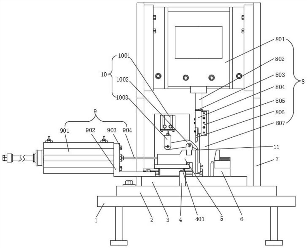
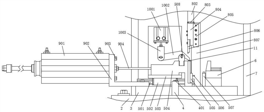
[0027] Such as Figure 1-Figure 7As shown, the specific structure of the present invention is: a terminal cutting and pressing device with an L-shaped punching head, including a workbench 1, a bottom plate 2 and a support frame 7, and the bottom plate 2 is connected and supported by a clamp block 4 and a clamping bolt 401. Plate 3, lower support plate 3 upper ends are provided with pusher assembly 9, slide block assembly 5 and workpiece limit seat 6 successively, pusher assembly 9 can push slide block assembly 5 close to workpiece limit seat 6, slide block assembly 5 and the top The clamping component...


PUM


Abstract

The invention discloses a terminal cutting-off and press-fitting device with an L-shaped stamping head, and relates to the technical field of terminal cutting-off and press-fitting. The terminal cutting-off and press-fitting device comprises a workbench, a bottom plate and a supporting frame, wherein the bottom plate is connected with a lower supporting plate through a clamping block and a clamping bolt, the upper end of the lower supporting plate is sequentially provided with a pushing assembly, a sliding block assembly and a workpiece limiting seat, the sliding block assembly is matched with a clamping assembly above to clamp terminals, each terminal is of a U-shaped linear array sheet structure, a cutting-off assembly is arranged at the side end of the clamping assembly and comprises the stamping head, and the lower end of the stamping head is of an L-shaped protruding structure and can be matched with the terminal. With the terminal cutting-off and press-fitting device with the L-shaped stamping head, the processing requirements of enterprises on large-batch terminal feeding, cutting and press-fitting are met, unqualified terminal cutting-off and press-fitting caused by misoperation of employees of the enterprises are avoided, then the rejection rate of the enterprises is reduced, the cutting-off and press-fitting efficiencies of the terminals are improved, and the phenomena of bending and unevenness of the terminals due to overlarge feeding thrust are effectively avoided.

Description

technical field [0001] The invention relates to the technical field of terminal cutting and pressing, in particular to a terminal cutting and pressing device with an L-shaped stamping head. Background technique [0002] Terminal block is an accessory product used to realize electrical connection, which is industrially divided into the category of connectors. With the increasing degree of industrial automation and stricter and more precise industrial control requirements, the amount of terminal blocks is gradually increasing. With the development of the electronics industry, the use of terminal blocks is increasing, and there are more and more types. In addition to PCB board terminals, the most widely used ones are hardware terminals, nut terminals, spring terminals and so on. [0003] At present, in the production and processing of terminals, it is necessary to use terminals with a U-shaped linear array sheet structure (as shown in the attached manual) figure 2 As shown),...

Claims


Application Information

Patent Timeline
IPC IPC(8): B23D15/04B23D15/14B23D33/02B23P19/027H01R43/16
CPCB23D33/02B23D15/04B23D15/14H01R43/16B23P19/027
Inventor 金代东
Owner YAXIN (HUAIHUA) ELECTRONICS CO LTD
Why Eureka
Try Eureka