Electron beam welding joint induction heating device

An induction heating device and electron beam welding technology, which is applied to electron beam welding equipment, high-frequency current welding equipment, welding equipment, etc., can solve the problems of slow cooling and inability to preheat

Active Publication Date: 2021-09-10
AECC AVIATION POWER CO LTD
View PDF4 Cites 0 Cited by
  • Summary
  • Abstract
  • Description
  • Claims
  • Application Information

AI Technical Summary

Problems solved by technology

[0003] In order to overcome the shortcomings of the above-mentioned prior art, the object of the present invention is to provide an induction heating device for electron beam welding joints, which can be welded through a reasonably designed auxiliary device, which solves the problem that preheating and welding before welding cannot be performed in the electron beam welding vacuum chamber. post-cooling problem

Method used

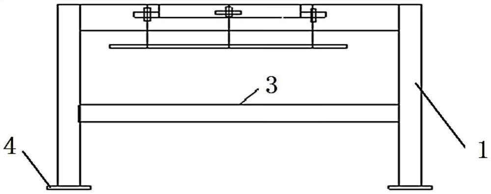
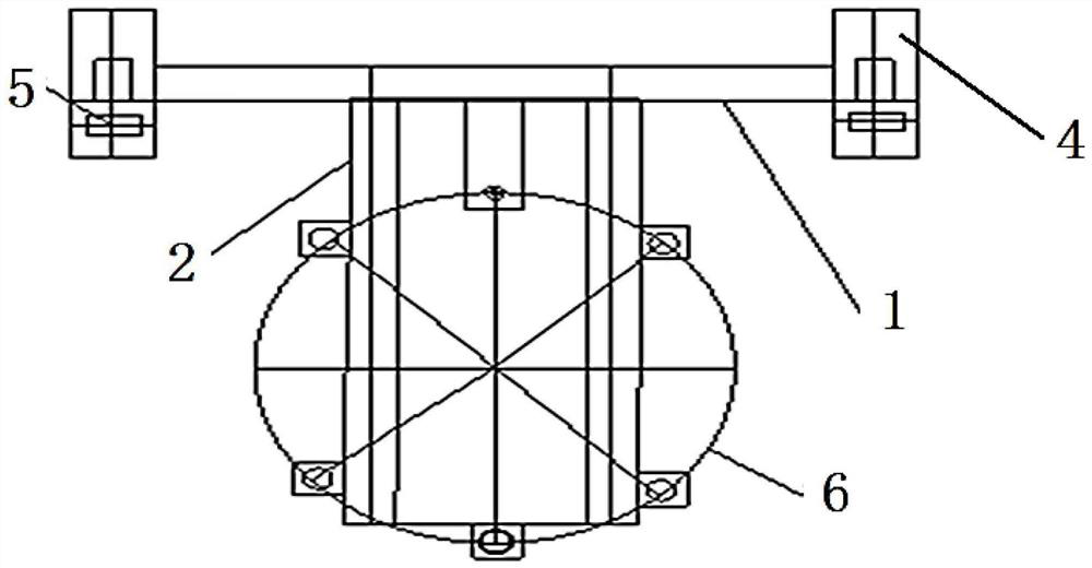
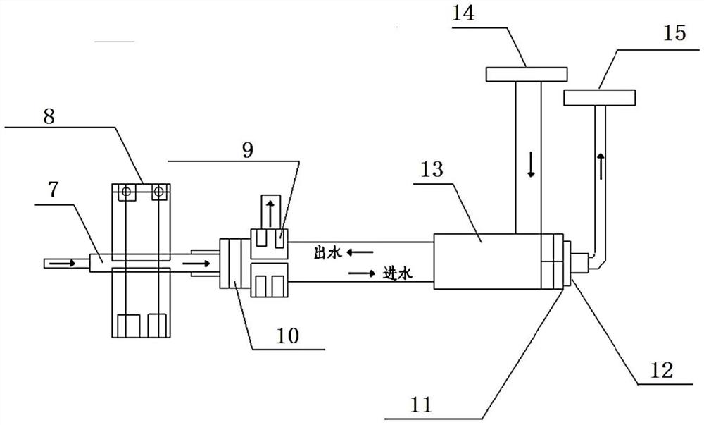

Image

  • Electron beam welding joint induction heating device
  • Electron beam welding joint induction heating device
  • Electron beam welding joint induction heating device

Examples


Embodiment Construction

[0023] In order to enable those skilled in the art to better understand the solutions of the present invention, the following will clearly and completely describe the technical solutions in the embodiments of the present invention in conjunction with the drawings in the embodiments of the present invention. Obviously, the described embodiments are only It is an embodiment of a part of the present invention, but not all embodiments. Based on the embodiments of the present invention, all other embodiments obtained by persons of ordinary skill in the art without making creative efforts shall fall within the protection scope of the present invention.

[0024] It should be noted that the terms "first" and "second" in the description and claims of the present invention and the above drawings are used to distinguish similar objects, but not necessarily used to describe a specific sequence or sequence. It is to be understood that the data so used are interchangeable under appropriate ...


PUM


Abstract

The invention discloses an electron beam welding joint induction heating device, and belongs to the technical field of electron beam welding. The induction heating device comprises a support body, wherein an extension support is arranged at the top of the support body, and an induction coil support is arranged on the extension support; a coaxial electrode comprises an inner pipe, one end of the inner pipe serves as a water inlet, the other end of the inner pipe communicates with one end of an outer pipe through an insulation locking nut, a pipeline is led out of the other end of the outer pipe to serve as a high-voltage electrode, a sealing sleeve is arranged between the other end of the outer pipe and the high-voltage electrode, and a pipeline is further led out of the outer side wall of the other end of the outer pipe to serve as a low-voltage electrode; an outer pipe clamping block is arranged on the outer side wall of the outer pipe, and a water outlet pipeline is arranged on the outer pipe clamping block; an inner pipe clamping block is arranged on the inner pipe; and an induction coil is arranged on the induction coil support, and the two ends of the leading-out end of the induction coil communicate with the high-voltage electrode and the low-voltage electrode of the coaxial electrode. The design structure is reasonable, and the problem that effective heat treatment cannot be conducted in an electron beam welding vacuum chamber is solved.

Description

technical field [0001] The invention belongs to the technical field of electron beam welding, and relates to an induction heating device for electron beam welding joints. Background technique [0002] As a special welding method, electron beam welding has the advantages of good welding accessibility, large penetration depth and good atmosphere, high joint strength, small welding deformation, large welding thickness, and a wide range of weldable materials. It is being used by more and more people. It is used in the manufacturing process of precision parts. The most important performance indicators of an engine are its thermal efficiency and thrust-to-weight ratio. The simplest and most effective way to improve these two performances is to replace nickel-based heat-resistant alloys with new materials that are lightweight and high-temperature resistant. Ti 2 As an intermetallic compound, AlNb material has attracted attention due to its advantages such as high specific strengt...

Claims


Application Information

Patent Timeline
IPC IPC(8): B23K13/02B23K15/00
CPCB23K13/02B23K15/0053
Inventor 杨卓勇王一迪王建涛康文军武建勋陈涛王涛张超
Owner AECC AVIATION POWER CO LTD
Why Eureka
Try Eureka