
Resistance adjusting machine and resistance adjusting method for electronic accelerator pedal circuit board

An electronic accelerator pedal, circuit board technology, applied in printed circuits, laser welding equipment, transportation and packaging, etc., can solve problems such as inconsistent electrical signals, different contact positions, and different degrees of contact between brushes and resistors.

Active Publication Date: 2021-09-10
NINGBO AUTO CABLE CONTROLS
View PDF5 Cites 0 Cited by
  • Summary
  • Abstract
  • Description
  • Claims
  • Application Information

AI Technical Summary

Problems solved by technology

[0004] However, due to the problem of assembly accuracy, such as the different contact degree and contact position between the brush and the resistor sheet, etc., there are inconsistencies in the output electrical signals when the swing arm swings at the same angle. Adjust the resistance value of one or more resistors, so that the output electrical signal is consistent when the swing arm swings at the same angle

Method used


Image

  • Resistance adjusting machine and resistance adjusting method for electronic accelerator pedal circuit board
  • Resistance adjusting machine and resistance adjusting method for electronic accelerator pedal circuit board
  • Resistance adjusting machine and resistance adjusting method for electronic accelerator pedal circuit board

Examples


Embodiment Construction

[0039] The present invention will be further described in detail below in conjunction with the accompanying drawings and embodiments.

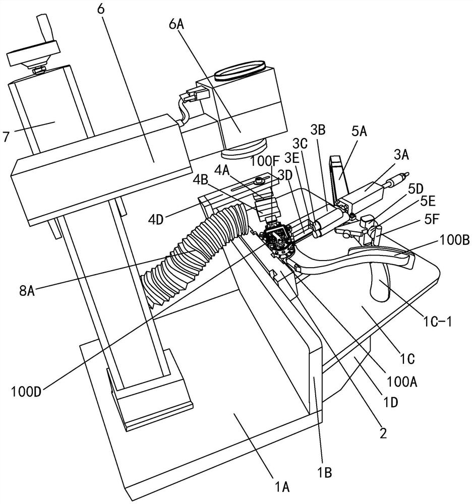
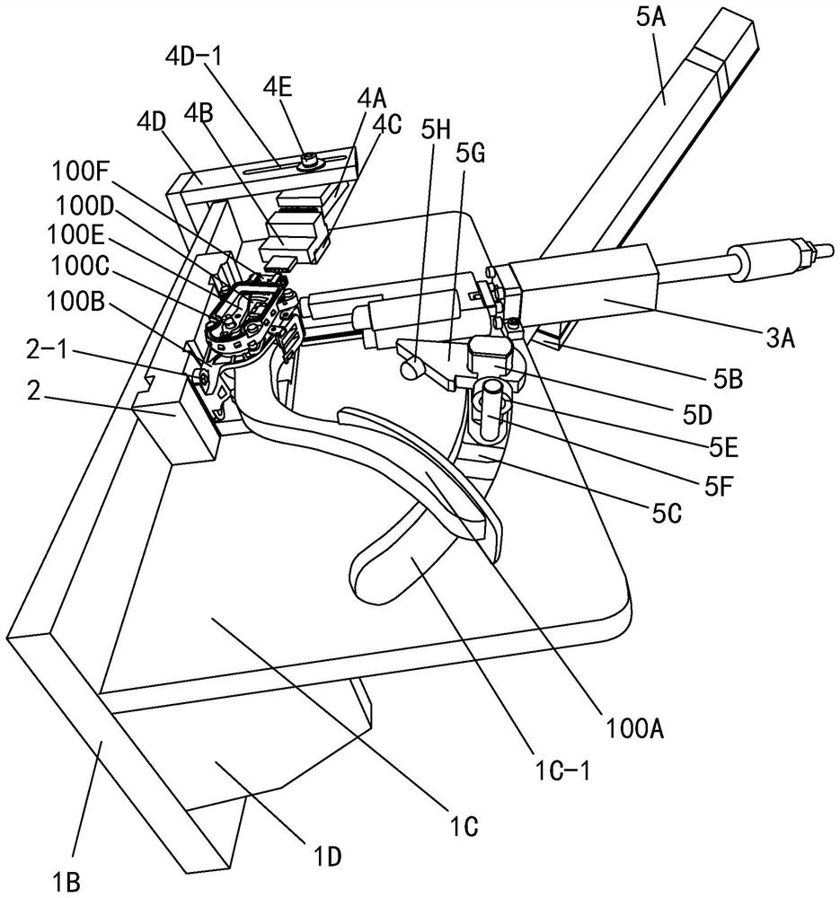
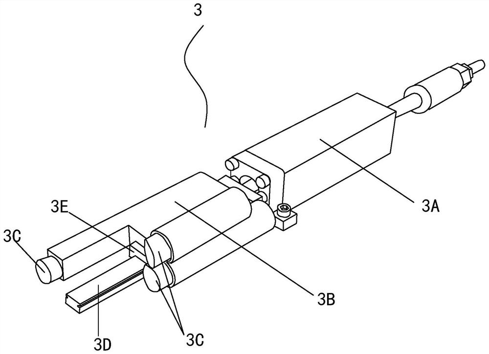
[0040] This preferred implementation is as figure 1 and 2Shown is a resistance adjustment machine for electronic accelerator pedal circuit board, including a controller (not shown in the figure), a frame, an electronic accelerator pedal assembly loading plate 2, an electronic accelerator pedal assembly locking mechanism 3, and a data connector connection mechanism 4 , Swing arm simulation pushing mechanism and laser machine 6. Wherein, the controller adopts a PLC controller, and the electric signal standard of the circuit board is preset in the PLC controller, and can calculate the parameters of each resistance sheet according to the received electric signal, and the controller can also adopt a computer. Wherein, the frame includes a base plate 1A, a riser 1B, a table 1C and a support plate 1D, the riser 1B is vertically fixed to the base pl...


PUM


Abstract

The invention discloses a resistance adjusting machine and a resistance adjusting method for an electronic accelerator pedal circuit board. The resistance adjusting machine and the resistance adjusting method for the electronic accelerator pedal circuit board have the advantages that an electronic accelerator pedal component to be subjected to resistance adjusting is propped against an electronic accelerator pedal component loading plate through an electronic accelerator pedal component locking mechanism, the circuit board is electrically connected with a controller through a data connector connecting mechanism, and therefore, an electric signal generated on the circuit board when a swing arm simulation pushing mechanism pushes a swing arm to simulate the treading condition is fed back to a controller; and the electric signal is compared with a standard signal preset in the controller, the controller controls a laser machine to carry out laser cutting on a resistor disc on the circuit board, the resistance value of the resistor disc is adjusted, and therefore, output electric signals are consistent under the condition that the swing arm swings at the same angle.

Description

technical field [0001] The invention belongs to the technical field of processing equipment and processing methods for automotive electronic accelerator pedal parts, and in particular relates to a resistance adjusting machine and a resistance adjusting method for an electronic accelerator pedal circuit board. Background technique [0002] With the rapid development of the automobile industry, the mechanical accelerator pedal for automobiles has been gradually replaced by the electronic accelerator pedal. The electronic accelerator pedal accurately controls the opening of the throttle valve by outputting electrical signals, thereby precisely controlling the combustion of fuel in the cylinder, resulting in higher energy efficiency and more environmentally friendly emissions; it is widely used in passenger cars, buses, trucks, engineering vehicles, new energy cars, sedans, and SUVs. [0003] The existing contact-type automotive electronic accelerator pedal includes components ...

Claims


Application Information

Patent Timeline
IPC IPC(8): B23K26/38B23K101/42
CPCB23K26/38B23K2101/006B23K2101/42
Inventor 石磊周志浩
Owner NINGBO AUTO CABLE CONTROLS
Learn More