
Damping device and method for restraining cutting chatter of machine tool spindle and machine tool spindle

A technology of machine tool spindle and damping device, applied in the direction of manufacturing tools, metal processing mechanical parts, large fixed members, etc., can solve the problems of large installation space, difficult to guarantee the damping effect, and can not meet the large-scale engineering application.

Pending Publication Date: 2021-09-10
XI AN JIAOTONG UNIV
View PDF13 Cites 1 Cited by
  • Summary
  • Abstract
  • Description
  • Claims
  • Application Information

AI Technical Summary

Problems solved by technology

Therefore, although the active chatter suppression method has excellent chatter suppression effects, it also faces disadvantages such as difficult design and high system cost in practical application, and cannot meet large-scale engineering applications. In contrast, passive chatter suppression The method design is relatively simple and the cost is relatively low, so it is still an important cutting chatter suppression method
[0004] However, the large installation space and difficulty in applying to a variety of working conditions are still the limiting factors for the passive flutter suppression method based on the damper. For example, the commonly used mass damper or extrusion The pressure oil film damper requires a large installation space. At the same time, when the dynamic characteristics of the spindle machining system change due to nonlinear factors such as changes in working conditions, its damping effect is difficult to be guaranteed, so it is difficult to apply to vibrations under various working conditions. vibration suppression

Method used


Image

  • Damping device and method for restraining cutting chatter of machine tool spindle and machine tool spindle
  • Damping device and method for restraining cutting chatter of machine tool spindle and machine tool spindle
  • Damping device and method for restraining cutting chatter of machine tool spindle and machine tool spindle

Examples


Embodiment Construction

[0030] The invention will be further described in detail below with reference to the accompanying drawings:

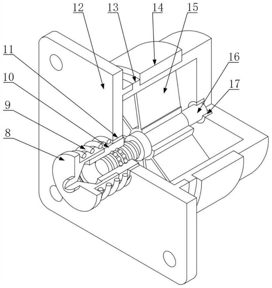
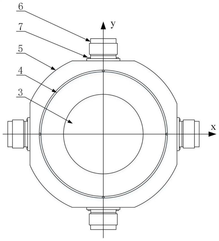
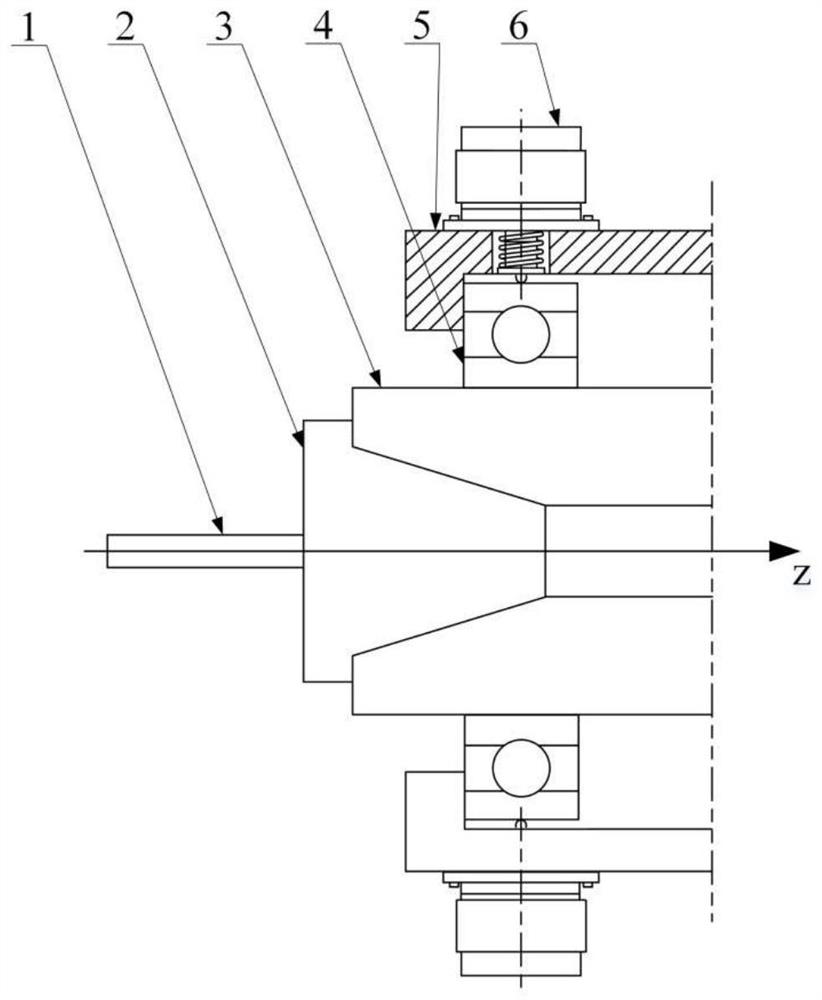
[0031] like figure 1 As shown, a damper device for suppressing the spindle cutting fibril of the machine tool, including the damper seat 13 of the ball screw 16 and the cylindrical structure, and the bottom of the damper seat 13 is provided with a rotating groove, and one end of the ball screw 16 is provided in rotation. In the groove, it is possible to rotate in the rotating groove, and the opening end of the damper seat 13 is provided with a ball screw nut 10, and the ball screw nut 10 is slidably connected. The other end of the ball screw 16 is coordinated with the ball screw nut 10. Connecting, the end portion of the ball screw nut 10 is fixedly connected to the across rod 8, and there is a caching spring 9 between the sidewall 8 and the damper 13, and the ball screw 16 is located in the damping seat 13 fixed to a fan blade 15, damping seat. 13 The internal charge is p...


PUM


Abstract

The invention discloses a damping device and method for restraining cutting chatter of a machine tool spindle and the machine tool spindle. Through a ball screw and a damping seat of a cylindrical structure, one end of the ball screw is arranged in a rotating groove, a ball screw nut is arranged at the open end of the damping seat, an ejector rod is fixedly connected to the end of the ball screw nut, the ejector rod slides in the axial direction under the cutting chatter effect of the spindle, the ejector rod drives the ball screw nut to slide in the axial direction, and the ball screw matched with the ball screw nut converts translation of the ejector rod into rotation, so that fan blades fixed to the ball screw are driven to rotate in a magnetorheological fluid, radial reciprocating vibration, caused by chatter, of a spindle system is converted into reciprocating rotation of the fan blades in the magnetorheological fluid through the ball screw and the fan blades, and vibration energy is dissipated under the action of damping force applied by the magnetorheological fluid. Damping of a machine tool system is changed, the structure is small and exquisite, and mounting is easy.

Description

Technical field [0001] The present invention belongs to the field of high-end intelligent machine, and more particularly to a damping apparatus, method, and machine spindle for suppressing machine spindle cutting fibrillation. Background technique [0002] The spindle system is a key unit of the CNC machine tool, and its state directly affects the quality of processing. Although the stiffness and accuracy of the machine spindle have reached a high technical level, the vibration in the spindle cutting process, especially the uncomfortable fluster, is still one of the important issues that are seriously affected by the quality of processing. As a self-invasive vibration phenomenon in the cutting process, it will not only generate severe noise, reduce processing efficiency, but will cause the surface processing of the workpiece to deteriorate, and even shorten the life of the machine tool. Obviously, how to suppress cutting vibration, ensure processing efficiency, improve processing...

Claims


Application Information

Patent Timeline
IPC IPC(8): B23Q11/00B23B19/02
CPCB23Q11/00B23Q11/0032B23Q1/70
Inventor 万少可奚航航李小虎方斌李阗岐洪军
Owner XI AN JIAOTONG UNIV
Learn More