Construction structure for slope monitoring and protection

A technology for slopes and protective caps, applied in the direction of foundation structure engineering, foundation structure tests, sheet pile walls, etc., can solve the problem that the anchorage structure does not have much functional improvement, cannot continue to measure, and the measurement range of the inclinometer is limited And other issues

Inactive Publication Date: 2021-09-10
CHINA MCC17 GRP
View PDF0 Cites 0 Cited by
  • Summary
  • Abstract
  • Description
  • Claims
  • Application Information

AI Technical Summary

Problems solved by technology

[0005] Aiming at the deficiencies of the prior art, the present invention provides a construction structure for slope monitoring and protection, which solves the problems of the existing slope measuring instruments, has high measurement accuracy, and can also realize automatic monitoring, but due to the limitation of the measurement principle , so that the measurement range of the inclinometer is limited. In the case of a large displacement change on the slope sliding surface, the measurement cannot be continued. The sensor of the inclinometer is arranged in the borehole for measurement. The sensing device and the data acquisition device It is connected by a data line, and when the sliding surface is frustrated by the inclinometer tube, it cannot continue to monitor; there are many kinds of existing anchor structures, but most of them are only changes in style, and their anchor structures do not have much function Improvement. When the existing anchoring structure is used, the insufficient strength of the rod body will lead to the loss of prestress, which cannot protect the displacement of the cracked and loose rock mass, and the exposed outer anchoring end will cause corrosion, which will affect the durability of the anchoring structure.

Method used


Image

  • Construction structure for slope monitoring and protection
  • Construction structure for slope monitoring and protection
  • Construction structure for slope monitoring and protection

Examples


Embodiment Construction

[0033] The following will clearly and completely describe the technical solutions in the embodiments of the present invention with reference to the accompanying drawings in the embodiments of the present invention. Obviously, the described embodiments are only some, not all, embodiments of the present invention. Based on the embodiments of the present invention, all other embodiments obtained by persons of ordinary skill in the art without making creative efforts belong to the protection scope of the present invention.

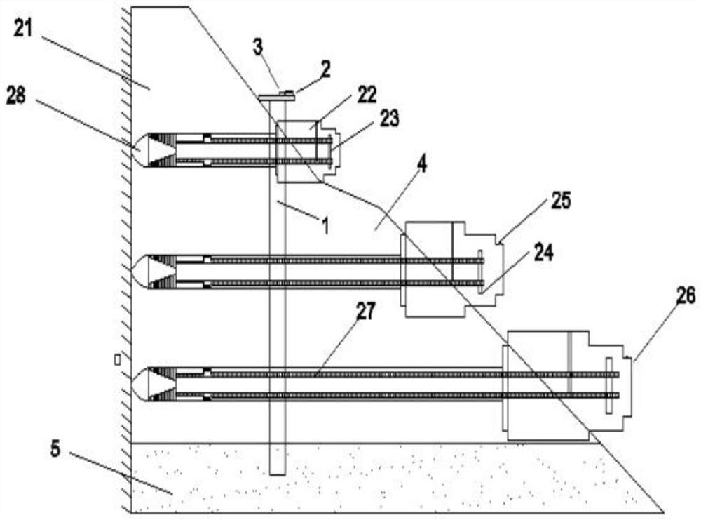
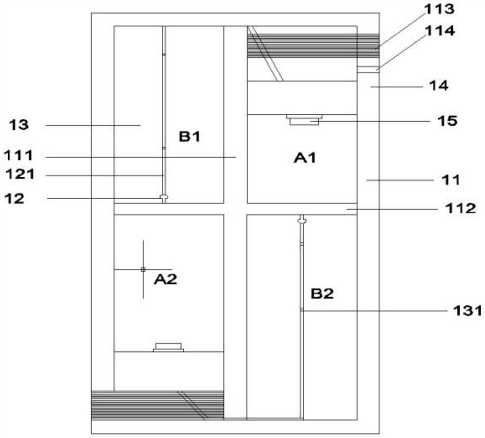
[0034] see Figure 1-4 , the present invention provides a technical solution: a construction structure for slope monitoring and protection, comprising a bedrock layer 5, a slope soil 4 is arranged on the bedrock layer 5, a landslide 21 is arranged on the slope soil 4, and a slope An inclinometer tube 1 is installed through the soil 4, the bottom end of the inclinometer tube 1 is inserted into the bedrock layer 5, and the top end of the inclinometer tube 1 is p...


PUM


Abstract

The invention discloses a construction structure for slope monitoring and protection, and relates to the technical field of building construction. The construction structure for slope monitoring and protection comprises a bedrock layer, slope soil is arranged on the bedrock layer, a landslide is arranged on the slope soil, an inclinometer pipe arranged on the slope soil in a penetrating manner is also included, the bottom end of the inclinometer pipe is inserted into the bedrock layer, and a power source and a wireless data transmitting device are arranged at the top end of the inclinometer pipe. According to the construction structure for slope monitoring and protection, a slope can be detected and protected, and the construction structure plays an important role in preventing collapse of unstable blocks, improving the stress state of the slope and improving the overall stability of the slope; and according to the influence of rainfall and underground water on the slope, the slope is divided into an upper part and a lower part to be independently monitored (the water content and the collapse angle of the slope are monitored), so that positioning treatment is carried out according to the water content conditions and the collapse conditions of the upper part and the lower part of the slope.

Description

technical field [0001] The invention relates to the technical field of building construction, in particular to a construction structure for slope monitoring and protection. Background technique [0002] The side slope refers to the slope with a certain slope on both sides of the roadbed to ensure the stability of the roadbed. The problem of slope stability has attracted much attention, and the monitoring and protection of slopes has become an indispensable part of slope construction. [0003] The existing slope inclinometers have high measurement accuracy and can also realize automatic monitoring. However, due to the limitation of the measurement principle, the measurement range of the inclinometer is limited. In the case of large displacement changes on the sliding surface of the slope, The measurement cannot be continued. The sensor of the inclinometer is arranged in the borehole for measurement. The sensor device is connected with the data acquisition device through a da...

Claims


Application Information

Patent Timeline
IPC IPC(8): E02D33/00E02D17/20E02D5/74E02D15/04E02D5/22
CPCE02D33/00E02D17/20E02D17/207E02D5/74E02D15/04E02D5/22E02D2600/10E02D2600/40E02D2600/30
Inventor 聂恩窦李盼钱元弟金仁才王瀚黄金坤
Owner CHINA MCC17 GRP
Why Eureka
Try Eureka