Oil pumping unit speed reducer with safety protection function
A technology of safety protection and deceleration device, which is applied in the direction of transmission device, gear transmission device, and components with teeth, etc., which can solve the problems of difficult deceleration shaft, affecting the safe use performance of pumping units, and large motor power
- Summary
- Abstract
- Description
- Claims
- Application Information
AI Technical Summary
Problems solved by technology
Method used
Image
Examples
Embodiment 1
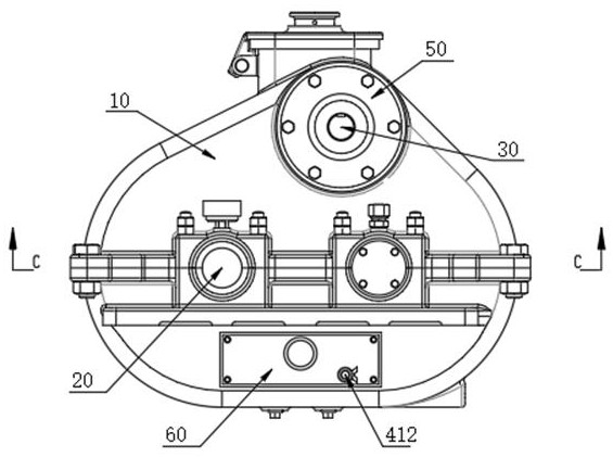
[0037] see Figure 1-3 As shown, a pumping unit deceleration device with safety protection function includes a casing 10, the interior of the casing 10 is provided with a deceleration shaft 20 for rotation, one end of the deceleration shaft 20 penetrates the casing 10 and extends to the outside of the casing 10 One end of the reduction shaft 20 located outside the casing 10 is provided with a reduction gear 40 , a fixed disk 50 is arranged above the front of the casing 10 , a motor 30 is arranged on the front of the fixed disk 50 , and one end of the output shaft of the motor 30 runs through the casing 10 And extend to the inside of the casing 10, the lower part of the front of the casing 10 is provided with a mounting plate 60;
[0038] The interior of the casing 10 is provided with a drive assembly, wherein the drive assembly includes a drive shaft 101, the drive shaft 101 is located in the interior of the casing 10 and connected in rotation, and one end of the drive shaft 1...
Embodiment 2
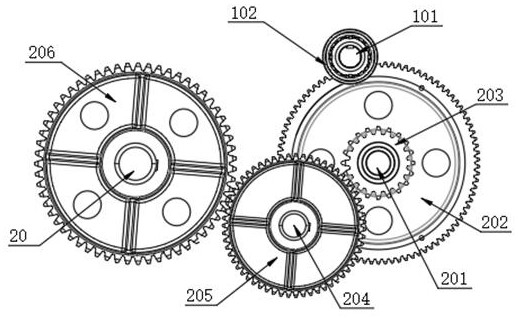
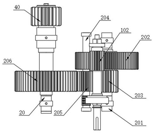
[0040] see Figure 2-4 As shown, the interior of the casing 10 in the present invention is also provided with a transmission assembly, the transmission assembly includes a transmission shaft 201, the surface of the transmission shaft 201 is provided with a first transmission wheel 202, and the first transmission wheel 202 and the drive wheel 102 The surfaces mesh with each other, and the driving wheel 102 itself rotates to drive the first transmission wheel 202 to rotate, thereby realizing the transmission output of the motor 30 to the reduction gear; The transmission shaft 2 204 is rotated, and the surface of the transmission shaft 204 is provided with a brake protection wheel 205, the brake protection wheel 205 and the surface of the second transmission wheel 203 mesh with each other, and the reduction shaft 20 is located on the surface inside the casing 10. There is a third transmission wheel 206, and the surface of the third transmission wheel 206 is meshed with the surfac...
Embodiment 3
[0042] see Figure 5 As shown, a positioning assembly is also provided between the inside of the second transmission wheel 203 and the transmission shaft 201 in the present invention, the positioning assembly includes two positioning blocks 301, and the surface of the transmission shaft 201 is symmetrically provided with two installation grooves 302, And the insides of the two mounting grooves 302 are provided with electric push rods 303, and the inside of the second drive wheel 203 is symmetrically provided with two positioning grooves 304 that are compatible with the positioning blocks 301, and the electric push rods 303 are used to push the positioning blocks 301 and Cooperate between the positioning grooves 304 to realize the positioning connection of the second transmission wheel 203 on the surface of the transmission shaft one 201. When the brake protection wheel 205 is used for braking, the positioning block 301 is moved from the positioning groove by the electric push r...
PUM
 Abstract
Description
Claims
Application Information
 - R&D
- Intellectual Property
- Life Sciences
- Materials
- Tech Scout
- Unparalleled Data Quality
- Higher Quality Content
- 60% Fewer Hallucinations
Browse by: Latest US Patents, China's latest patents, Technical Efficacy Thesaurus, Application Domain, Technology Topic, Popular Technical Reports.
© 2025 PatSnap. All rights reserved.Legal|Privacy policy|Modern Slavery Act Transparency Statement|Sitemap|About US| Contact US: help@patsnap.com


