Self-installation and self-recovery micro-seismic sensor device
What is Al technical title?
Al technical title is built by PatSnap Al team. It summarizes the technical point description of the patent document.
A microseismic sensor, self-recovery technology, applied in the field of geotechnical engineering, can solve the problems of high sensor price, waste of consumables, complex construction environment, etc.
Active Publication Date: 2021-09-10
DALIAN UNIV OF TECH
View PDF8 Cites 0 Cited by
Summary
Abstract
Description
Claims
Application Information
AI Technical Summary
This helps you quickly interpret patents by identifying the three key elements:
Problems solved by technology
Method used
Benefits of technology
Problems solved by technology
As the face advances, the sensor needs to be moved forward continuously. Usually, the sensor can only be screwed out by using the installation rod, but it is difficult to remove the sensor because the cement anchor or resin anchor is fixed in the hole, and each sensor is expensive , greatly increasing the cost of microseismic monitoring
Moreover, the construction environment is complicated. Once the sensor has a monitoring problem, it is difficult to repair it. It can only be re-drilled and replaced with a new sensor. This not only wastes time and money, but also affects the quality of monitoring and delays the construction of workers.
[0004] In recent years, there have been some installation devices and methods for microseismic sensors, such as adding a sleeve outside the sensor and fixing it with cement, or using airbags or expansion agents to fix the ...
Method used
Image
Click on the blue label to locate the original text in one second.
Reading with bidirectional positioning of images and text.
Examples
Embodiment 1
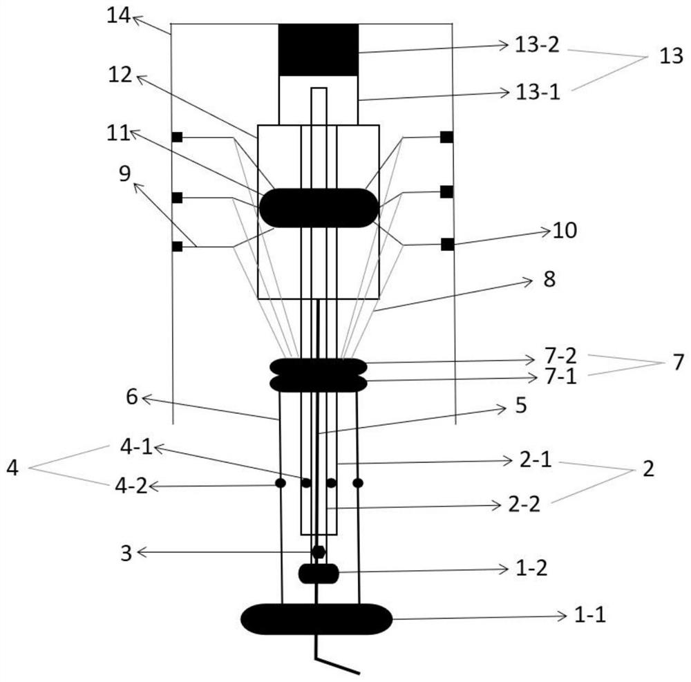
[0025] A self-installation and self-recovery microseismic sensor device, comprising: handle A1-1, handle B1-2, outer middle rod 2-1, inner middle rod 2-2, dynamometer 3, expansion joint 4, cable 5, Thrust rod 6, connection disc 7, elastic rod 8, bracket 9, elastic film 10, fixed disc 11, sensor 12, elastic probe 13, the handle A1-1 is connected with the thrust rod 6, and the thrust rod 6 It is connected with the connecting plate 7, the connecting plate 7 is connected with the elastic rod 8, the elastic rod 8 is connected with several supports 9, one end of the support 9 is connected with the fixed plate 11, and the other end is connected with the fixed plate 11. The elastic film 10 is connected; the handle B1-2 is connected with the inner middle rod 2-2, the inner middle rod 2-2 is built in the outer middle rod 2-1, and the connecting plate 7 is connected with the inner middle rod 2-2. The outer middle rod 2-1 built in the thrust rod 6 is movably connected, the sensor 12 is co...
Embodiment 2
[0032] A self-installation and self-recovery microseismic sensor device includes four systems, namely a control system, a monitoring system, a fixing system and a force transmission system.
[0033] 1 Control system includes: handle A1-1, handle B1-1, middle rod 2 includes outer middle rod 21-, inner middle rod 2-2, dynamometer 3, expansion joint 4 includes middle rod expansion joint 4-1, thrust Rod expansion joint 4-2.
[0034] 2. The monitoring system includes: cables 5, sensors 12, elastic probes 13 including elastic chambers 13-1 and sensitive probes 13-2.
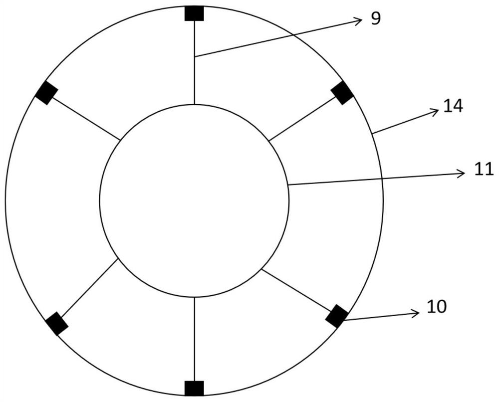
[0035] 3 The fixing system includes: a bracket 9, an elastic film 10, and a fixing plate 11.
[0036] 4. The force transmission system includes: a thrust rod 6, a connection plate 7, a bottom 7-1 of the connection plate, a top 7-2 of the connection plate, and an elastic rod 8.
[0037] The handle A1-1 is connected to the push rod 6, the push rod 6 is connected to the connection plate 7, the connection plate 7 is connec...
PUM
Abstract
The invention discloses a self-installation and self-recovery micro-seismic sensor device, and belongs to the technical field of geotechnical engineering. According to the device, a handle A is connected with a thrust rod, the thrust rod is connected with a connecting disc, the connecting disc is connected with an elastic rod, the elastic rod is connected with a plurality of supports, one end of each support is connected with a fixing disc, and the other end of each support is connected with an elastic film; a handle B is connected with an inner middle rod, the inner middle rod is arranged in an outer middle rod, the connecting disc is movably connected with the outer middle rod arranged in the thrust rod, a sensor is connected with the connecting disc, the inner middle rod is connected with an elastic probe, one end of a cable is connected with the sensor, the other end of the cable is connected with an acquisition station, and a dynamometer is arranged on the inner middle rod; and telescopic joints for extending the lengths of the thrust rod and the outer middle rod are arranged on the thrust rod and the outer middle rod. The device has the beneficial effects that reinforcement of an anchoring agent is eliminated through an elastic device, and consumables do not need to be wasted; the sensor is tightly contacted with a rock mass, and the monitoring effect is good; when the rock mass deforms, the supports of the sensor and the elastic probe can be automatically adjusted, and the phenomenon of poor contact is avoided.
Description
technical field [0001] The invention belongs to the technical field of geotechnical engineering, in particular to a self-installation and self-recovery microseismic sensor device. Background technique [0002] Microseismic monitoring technology is an advanced technology that directly predicts the instability of large-scale engineering rock mass. It can judge the stress state inside the rock mass through the characteristic of acoustic emission of rock fracture, and capture the time, location and magnitude, so as to analyze the local damage location of the rock mass and the potential area of rockburst. In recent years, microseismic monitoring technology has been widely used in engineering practice, such as Hujiahe Coal Mine, Ashele Copper Mine, Hongtoushan Copper Mine, Baihetan Hydropower Station, Jinping Secondary Hydropower Station, Han River to Wei River Project, etc. [0003] However, before the microseismic monitoring, the acceleration sensor of the microseismic monito...
Claims
Application Information
Patent Timeline
Application Date:The date an application was filed.
Publication Date:The date a patent or application was officially published.
First Publication Date:The earliest publication date of a patent with the same application number.
Issue Date:Publication date of the patent grant document.
PCT Entry Date:The Entry date of PCT National Phase.
Estimated Expiry Date:The statutory expiry date of a patent right according to the Patent Law, and it is the longest term of protection that the patent right can achieve without the termination of the patent right due to other reasons(Term extension factor has been taken into account ).
Invalid Date:Actual expiry date is based on effective date or publication date of legal transaction data of invalid patent.