Method for extracting three-dimensional coordinate values from image in robot scene

A three-dimensional coordinate, robot technology, applied in image enhancement, image analysis, image data processing and other directions, can solve the problems of shaking, value accuracy is not high enough, low efficiency and so on

Pending Publication Date: 2021-09-10
安徽工布智造工业科技有限公司
View PDF0 Cites 0 Cited by
  • Summary
  • Abstract
  • Description
  • Claims
  • Application Information

AI Technical Summary

Problems solved by technology

[0003] Usually, a coordinate point in a three-dimensional world can be transformed by the robot transformation matrix to find a corresponding pixel point in the image, but it is very difficult to find its corresponding point in three dimensions through a point in the image. Existing The method used in the technology uses traditional images to obtain coordinate point values ​​with insufficient accuracy and low efficiency. Usually, it is difficult to obtain accurate Z-direction coordinates when obtaining image points. It is not easy to quickly convert image 2D coordinates into world 3D coordinates. Due to the size of the camera Limitation, the effective working range is fixed, it cannot adapt to large-area and large-size components, and it cannot meet the needs of some scenes that require high point-taking accuracy, such as welding
[0004] Usually, in the process of switching according to different points of the positioning camera, the outer shell and the inner shell slide against each other, and after multiple operations, the inner wall will cause excessive friction. Therefore, when positioning the coordinates, the side wall of the camera is prone to loosening and slipping. Due to the situation, there will be errors in the positioning coordinates. When the light switches, the sliding between the outer shell and the inner shell will easily cause the base to shake due to excessive force

Method used


Image

  • Method for extracting three-dimensional coordinate values from image in robot scene
  • Method for extracting three-dimensional coordinate values from image in robot scene
  • Method for extracting three-dimensional coordinate values from image in robot scene

Examples


Embodiment 1

[0044] see Figure 1-3 , a method for extracting three-dimensional coordinate values ​​from an image for a robot scene, comprising the following steps:

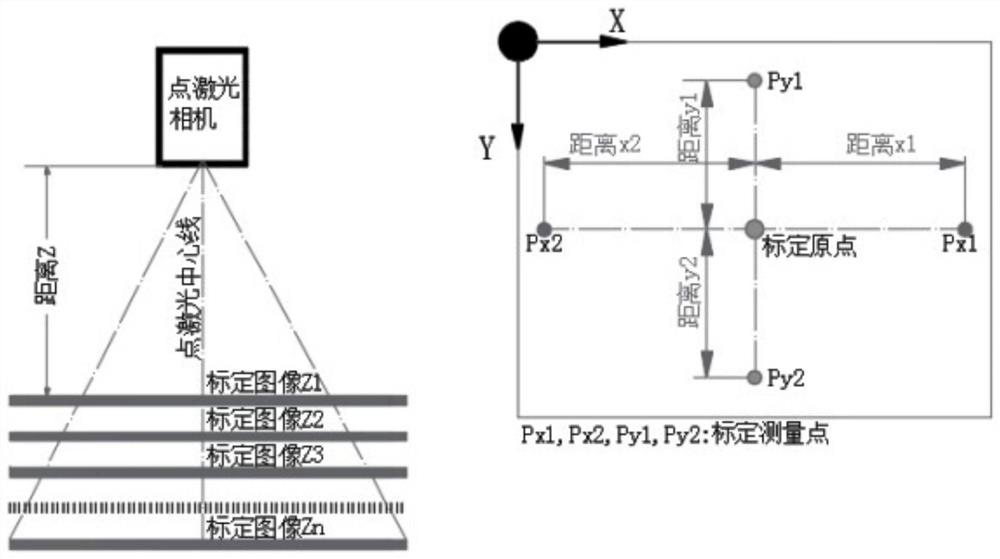
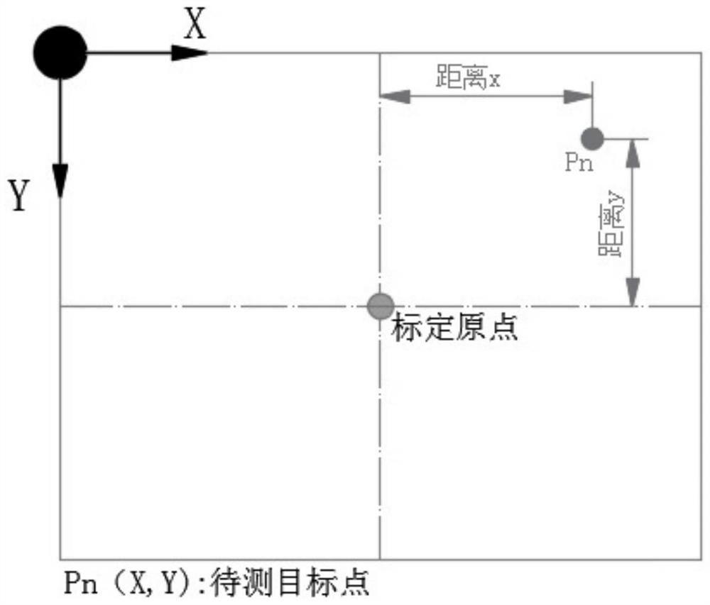
[0045] S1. Layered modeling is performed on the XY plane images at different heights (Z) from the camera to the target surface. The Z-direction interval of the sampled image is properly encrypted according to the usage requirements. Generally, ten steps are taken to form an image interpolation model. The interpolation model data structure mainly includes the distance Z between the camera lens and the target surface, the pixel XY position of the origin on the image, the X-direction proportional coefficient and the Y-direction proportional coefficient between the pixel and the physical length, etc.;

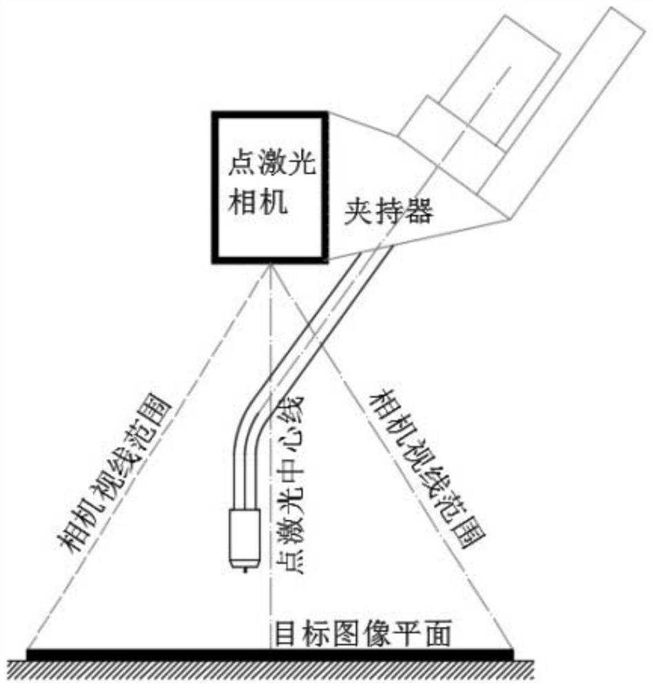
[0046] S2. The camera and the point laser are fixedly installed at a suitable position at the end of the robot, and the direction of the point laser is kept parallel to the line of sight of the camera.

[0047] The camera and poi...

Embodiment 2

[0074] see Figure 4 and Figure 6 , a camera docking bracket auxiliary device for extracting information from a robot scene, including a support plate mechanism 1, the interior of the support plate mechanism 1 includes a base 111, the top of the base 111 is connected with a stacked plate 112, and the side wall of the stacked plate 112 is A support frame 113 is connected through it, and a movable ring 2 is connected through the top of the stretching plate mechanism 1, and a tank pushing mechanism 3 is slidably connected to the inner wall of the moving ring 2. The inside of the tank pushing mechanism 3 includes an expansion tube 311, and A superimposed network 312 runs through the axis of the inner side wall, a central column 315 runs through the axis of the inner side wall of the superimposed network 312, and a ball 314 runs through the side walls of the expansion tube 311, and the top and side walls of the ball 314 run through Connected with support rod 313, the bottom end o...

Embodiment 3

[0079] see Figure 4-5 , a camera docking bracket auxiliary device for extracting information from a robot scene, comprising a brace mechanism 1, a movable ring 2 connected through the top of the brace mechanism 1, and a tank push mechanism 3 slidingly connected to the inner wall of the movable ring 2, The interior of the tank pushing mechanism 3 includes an expansion tube 311, the inner side wall axis of the expansion tube 311 is connected with a superimposed net 312, and the inner side wall axis of the superimposed net 312 is connected with a central column 315, and the side wall of the expansion tube 311 There are balls 314 connected between them, the top and side walls of the balls 314 are connected with struts 313, the bottom end of the side wall of the movable ring 2 is connected with a connecting ring 9, and the middle part of the inner side wall of the movable ring 2 is connected with a movable disc 6. The side wall of movable disc 6 is connected with movable rod 7, an...


PUM


Abstract

The invention relates to the technical field of coordinate value extraction, and discloses a method for extracting three-dimensional coordinate values from an image in a robot scene. The method comprises the following steps: performing layered modeling on XY plane images of a camera at different heights (Z) from a target surface, fixedly mounting the camera and a point laser on proper positions at the tail end of a robot, moving the robot and an additional shaft in a photographing posture to make a real-time image center cross line fall on a target point, and obtaining the a three-dimensional coordinate values of a certain point on any plane under the condition that the sight line of a camera is basically perpendicular to a target surface. The method is used for rapidly and accurately obtaining the three-dimensional coordinate value of any position point on the target image, and is beneficial for the robot to carry out operation path planning. The point taking precision is high, the welding precision requirement of the robot can be met, intelligent target feature path extraction can be conducted on a static image through the image processing technology, and the connected device can avoid sliding displacement in the coordinate positioning process due to excessive smoothness.

Description

technical field [0001] The invention relates to the technical field of extracting coordinate values, in particular to a method for extracting three-dimensional coordinate values ​​from images in a robot scene. Background technique [0002] Using a robot for welding work, quickly obtaining the actual path coordinates of the target weld is the key task. Using the teach pendant for interactive operation is far from satisfying the automatic continuous operation of the robot. It is easy to generate pixel coordinates in the image coordinate system from the world coordinate system, but Extracting pixel coordinates from the image coordinate system, and then performing a series of coordinate transformations to generate three-dimensional coordinate values ​​in the world coordinate system is not easy to achieve. This requirement is very urgent in robot application scenarios. If the target position can be quickly extracted The path coordinates make it possible to apply robot operations ...

Claims


Application Information

Patent Timeline
IPC IPC(8): G06T7/80G06T7/73G06T3/40
CPCG06T7/80G06T7/75G06T3/4007G06T2207/30244
Inventor 郭家友王继文侯克文王伟昌
Owner 安徽工布智造工业科技有限公司
Why Eureka
Try Eureka