
Method for eliminating sampling delay error in motor system controlled by single current sensor
A delay error, single current technology, applied in control systems, control generators, vector control systems, etc., can solve problems such as increasing the controller's computing burden, complex algorithms, and inability to measure the accuracy of motor parameters
- Summary
- Abstract
- Description
- Claims
- Application Information
AI Technical Summary
Problems solved by technology
Method used
Image

Examples
Embodiment Construction
[0036] The technical solution of the present invention will be further described below in conjunction with the accompanying drawings, but it is not limited thereto. Any modification or equivalent replacement of the technical solution of the present invention without departing from the spirit and scope of the technical solution of the present invention should be covered by the present invention. within the scope of protection.
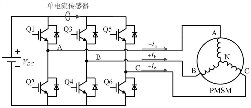
[0037] figure 1 is the circuit topology and the installation position of the single current sensor in the method of the present invention. Such as figure 1 As shown, the single current sensor is installed on a branch of the inverter, specifically between the switching tubes Q1 and Q3. Q1, Q2, Q3, Q4, Q5, and Q6 are the six switch tubes that constitute the three-phase voltage source inverter, V dc is the DC bus voltage, A, B, and C are the three-phase windings of the permanent magnet synchronous motor, N is the neutral point of the motor winding, and ...
PUM
 Abstract
Description
Claims
Application Information