Bearing forge piece cooling device
A technology of cooling device and water cooling device, which is applied in the field of bearing processing, and can solve the problems of reducing the air cooling effect of bearing forgings and good ventilation
- Summary
- Abstract
- Description
- Claims
- Application Information
AI Technical Summary
Problems solved by technology
Method used
Image
Examples
Embodiment 1
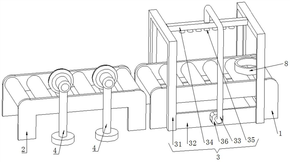
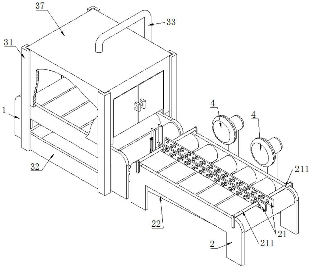
[0047] Such as Figure 2-6 As shown, a bearing forging cooling device includes a water-cooling conveyor 1 , an air-cooling conveyor 2 , a water-cooling device 3 , an air-cooling device 4 , and a turning mechanism 5 .
[0048] Both the water-cooled conveyor 1 and the air-cooled conveyor 2 can use chain conveyors or roller conveyors. The water-cooled conveyor 1 and the air-cooled conveyor 2 are sequentially placed on the ground.
[0049] The water cooling device 3 includes a water cooling frame 31 , a protective box 37 , a collection tank 32 , a water delivery pipe 33 , a water distribution pipe 34 , a nozzle 35 , and a water pump 36 . The upper end of the water-cooling frame 31 is welded with a protective box 37 , and the lower end of the water-cooling frame 31 is welded with a collecting tank 32 , and the water-cooling conveyor 1 is arranged between the protective box 37 and the collecting tank 32 . One end of the water delivery pipe 33 is welded and fixed with the tank wall...
Embodiment 2
[0062] Such as Figure 7-8 As shown, this embodiment 2 makes further improvements on the basis of embodiment 1.
[0063] In the bearing forging cooling device of the second embodiment, an auxiliary spraying mechanism 6 is also included.
[0064] The auxiliary spray mechanism 6 includes an auxiliary telescopic rod 61, an auxiliary vertical rod 62, an auxiliary cross bar 63, a first spray seat 64, a second spray seat 65, a first auxiliary spray head 66, a second auxiliary spray head 67, and connecting hoses. 68. Auxiliary hose 69.
[0065] Auxiliary telescopic link 61 also adopts electric push rod, and auxiliary telescopic link 61 is located at the outside of protective case 37, and the lower end of auxiliary telescopic link 61 and protective case 37 are welded and fixed.
[0066] The upper end of protective box 37 is provided with mounting hole 371, and the upper end of auxiliary vertical rod 62 passes mounting hole 371, and the upper end of auxiliary vertical rod 62 is welde...
Embodiment 3
[0074] Such as Figure 9-10 Shown, present embodiment 3 makes further improvement on the basis of embodiment 2:
[0075] In the cooling device for bearing forgings in Embodiment 3, the auxiliary spray mechanism 6 further includes a radial adjustment assembly 7 .
[0076] The radial adjustment assembly 7 is arranged in the protective box 37 , and the radial adjustment assembly 7 includes an adjustment sliding cylinder 71 , an adjustment telescopic rod 72 , an adjustment rod 73 , and an adjustment connecting rod 74 .
[0077] The adjusting sliding cylinder 71 is sheathed on the auxiliary vertical rod 62 , and the adjusting sliding cylinder 71 can slide up and down along the auxiliary vertical rod 62 .
[0078] Adjust telescoping link 72 and also adopt electric push rod, the upper end of regulating telescoping link 72 is welded and fixed with auxiliary vertical bar 62, and the lower end of regulating telescopic link 72 is welded and fixed with adjusting slide tube 71.
[0079] ...
PUM
 Abstract
Description
Claims
Application Information
 - R&D
- Intellectual Property
- Life Sciences
- Materials
- Tech Scout
- Unparalleled Data Quality
- Higher Quality Content
- 60% Fewer Hallucinations
Browse by: Latest US Patents, China's latest patents, Technical Efficacy Thesaurus, Application Domain, Technology Topic, Popular Technical Reports.
© 2025 PatSnap. All rights reserved.Legal|Privacy policy|Modern Slavery Act Transparency Statement|Sitemap|About US| Contact US: help@patsnap.com


