Engine flywheel assembling device and method
A technology for assembling devices and engines, which is applied in metal processing, metal processing equipment, manufacturing tools, etc., and can solve problems such as low degree of automation, slipping, and easy tumbling.
- Summary
- Abstract
- Description
- Claims
- Application Information
AI Technical Summary
Problems solved by technology
Method used
Image

Examples
Embodiment 1
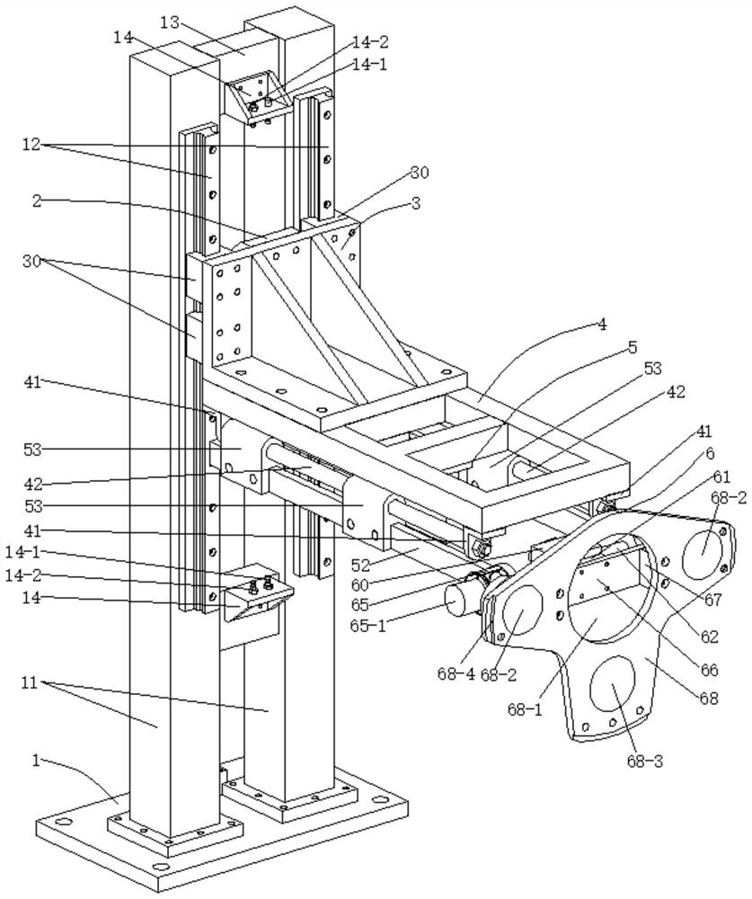
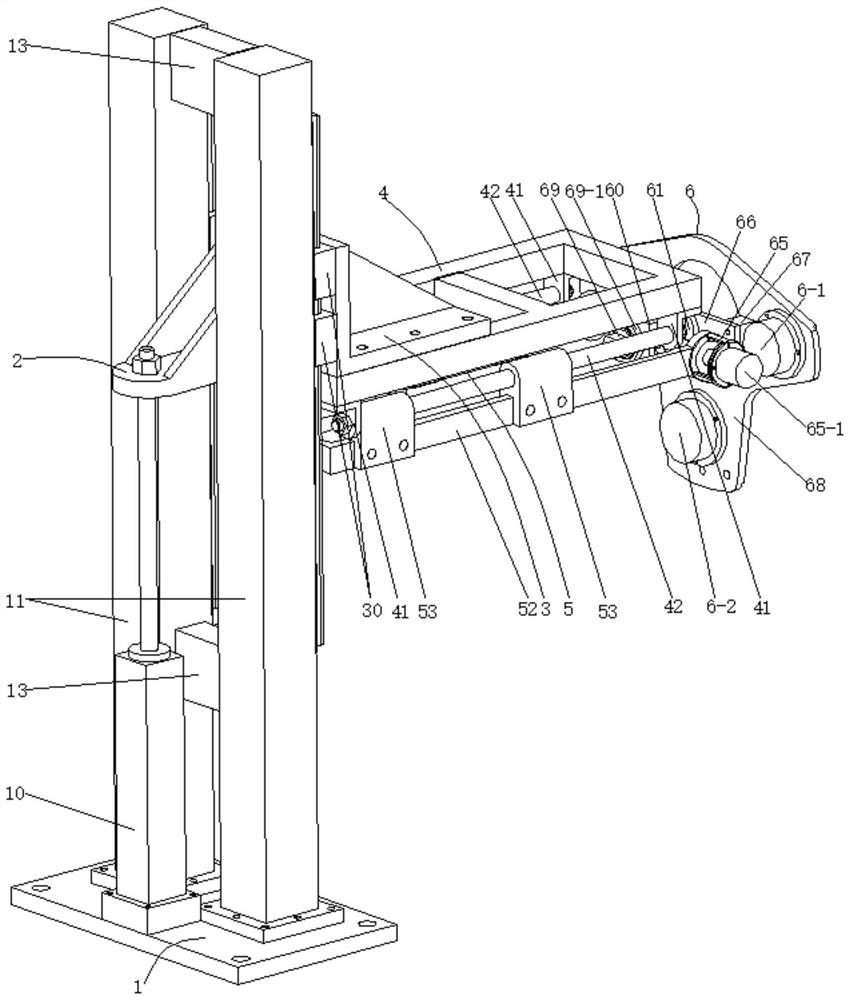
[0088] The engine flywheel assembling device includes a base plate 1, a rear connecting seat 2, a front connecting seat 3, a cantilever frame 4, a push mechanism 5 and a rotating connecting mechanism 6. The base plate 1 is provided with a main cylinder 10 and two column frames. 11. A guide rail 12 is provided on the front arm surface of the column frame 11, the rear connecting seat 2 is tightly connected with the rear arm surface of the front connecting seat 3, and the end of the piston rod of the master cylinder 10 is tightly connected with the rear connecting seat 2. A sliding block 30 is provided on the rear arm surface of the front connecting seat 3, the sliding block 1 30 is slidably connected with the guide rail 1 12, the cantilever frame 4 is firmly connected with the front connecting seat 3, and the pushing The mechanism 5 is connected with the cantilever frame 4, and the rotary connection mechanism 6 is connected with the push mechanism 5; through the contraction and e...
Embodiment 2
[0090] On the basis of Embodiment 1, the upper end and the lower end between the column frames 11 are respectively provided with cross braces 13 , the cross brace 13 at the upper end is provided with an upper limit seat 14 , and the upper limit seat 14 is provided with The upper buffer 14-1 and the upper limiter 14-2 ensure that when the flywheel connecting disc 68 in the rotary connection mechanism 6 moves with the engine flywheel to the uppermost end, the centerline of the engine flywheel is aligned with the centerline of the engine crankshaft; the lower end There is a lower limit seat 15 on the cross brace 13, and the lower limit seat 15 is provided with a lower buffer 15-1 and a lower limiter 15-2, which ensures that the flywheel connection plate 68 in the rotary connection mechanism 6 moves to At the lowermost end, the boss 68-4 provided at the bottom of the flywheel connecting plate 68 just snaps into the engine flywheel to avoid damage to the surface of the engine flywhe...
Embodiment 3
[0092] On the basis of Embodiment 1, a trigger seat 40 is provided in the middle of the rear end of the cantilever frame 4 to ensure the precise position limit of the upper limiter 14-2 and the lower limiter 15-2; the bottom of the cantilever frame 4 is provided with four There are two corner seats 41, and two guide rails 42 are arranged between the front and rear corner seats 41 on each side; 50 is tightly connected with the cantilever frame 4, the cylinder body of the auxiliary cylinder 51 is firmly connected with the connecting seat 50, the end of the piston rod of the auxiliary cylinder 51 is firmly connected with the middle part of the rear end of the gantry 52, the slider The second 53 is firmly connected with the gantry 52, and the second sliding block 53 is slidably connected with the second guide rail 42. The piston rod of the auxiliary cylinder 51 is retracted or extended, and the second sliding block 53 along the second guide rail 42 with the gantry 52 and its second...
PUM
 Abstract
Description
Claims
Application Information
 - R&D
- Intellectual Property
- Life Sciences
- Materials
- Tech Scout
- Unparalleled Data Quality
- Higher Quality Content
- 60% Fewer Hallucinations
Browse by: Latest US Patents, China's latest patents, Technical Efficacy Thesaurus, Application Domain, Technology Topic, Popular Technical Reports.
© 2025 PatSnap. All rights reserved.Legal|Privacy policy|Modern Slavery Act Transparency Statement|Sitemap|About US| Contact US: help@patsnap.com