
Tower type continuous flow reactor and application thereof

A reactor and tower technology, applied in the field of tower continuous flow reactors, can solve the problems of large footprint and complicated operation of the reactor, and achieve the effects of convenient regulation, the same stirring rate and improving the reaction rate.

Pending Publication Date: 2021-09-17
ZHEJIANG UNIV OF TECH
View PDF10 Cites 4 Cited by
  • Summary
  • Abstract
  • Description
  • Claims
  • Application Information

AI Technical Summary

Problems solved by technology

However, the existing reactor still has problems such as large reactor area and complicated operation.

Method used


Image

  • Tower type continuous flow reactor and application thereof
  • Tower type continuous flow reactor and application thereof

Examples


Embodiment

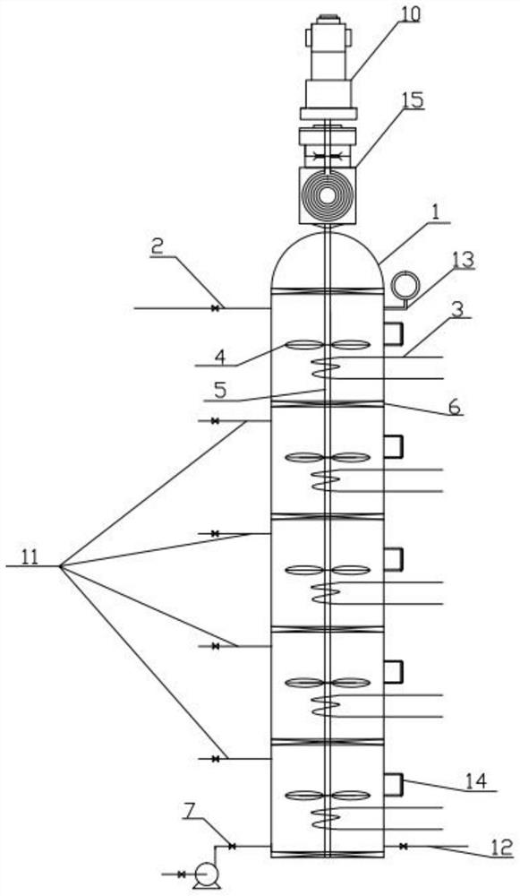
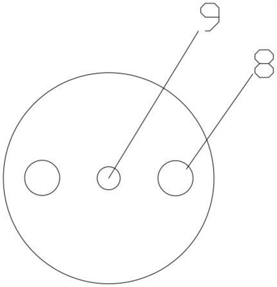
[0024] Example: Control Figure 1-2

[0025] A tower-type continuous flow reactor, comprising a reactor 1 in a tower structure, a motor 10 is arranged on the top of the reactor 1, and a stirring shaft 5 is connected to the motor 10; a plurality of partitions are arranged in the reactor 1 at intervals from bottom to top Plate 6, divider 6 divides reactor 1 into several reaction chambers, and each divider 6 is provided with a plurality of lifting holes 8 and an axis hole 9 for passing through the stirring shaft 5, and the plurality of The shaft holes 9 on the dividing plate 6 are located on the same vertical line. The lower end of the stirring shaft 5 extends into the reactor 1 from the top of the reactor 1, and extends to the bottom of the reactor 1 through the shaft hole 9 on the dividing plate 6; in the reactor 1, on the stirring shaft 5 in each reaction chamber Each is fixed with at least one layer of stirring blades 4, and the ratio of the outer diameter of the stirring b...

Embodiment 1

[0033] Such as Figure 1-2 As shown, a tower type continuous flow reactor, the reactor is a tower structure, 4 partitions are arranged in the reactor, and the reactor is divided into five reaction chambers by 4 partitions, and each partition is provided with There are two lifting holes and a shaft hole, the diameter of the lifting hole is 25mm, and the diameter of the shaft hole is 140mm. The inner diameter of the tower of the reactor is 1 meter, and the height of each reaction chamber is 0.5 meters.

[0034] A coil heat exchanger is installed in each reaction chamber, and the heat exchange area of ​​the coil heat exchanger is 1m 2 The temperature in each reaction chamber is controlled by adjusting the flow rate of the heat exchange medium in the coil heat exchanger. Each reaction chamber is provided with a sampling port and a temperature measuring port, and a valve is provided at the sampling port.

[0035] A motor is provided on the top of the reactor, and the motor is co...


PUM


Abstract

The invention discloses a tower type continuous flow reactor and application thereof. The tower type continuous flow reactor is characterized in that amotor is arranged at the top of the reactor, and is connected with a stirring shaft, the interior of the reactor is divided into a plurality of reaction chambers by partition plates, a plurality of liquid lifting holes and a shaft hole are formed in the partition plate, the stirring shaft extends to the bottom of the reactor through the shaft hole, a liquid sequentially passes through each reaction chamber of the reactor from bottom to top through the liquid lifting holes in the partition plate for reaction, in the reactor, each reaction chamber is internally provided with a layer of stirring blades, all the stirring blades are connected to the same stirring shaft, the motor drives the stirring shaft to rotate, then the stirring shaft drives the stirring blades to rotate, each reaction chamber is internally provided with a coil pipe heat exchanger, and the reaction temperature in each reaction chamber can be independently controlled. The device disclosed by the invention is small in occupied area, relatively low in cost and convenient to regulate and control, and can be applied to continuous production occasions of various reactions.

Description

technical field [0001] The application relates to the field of chemical equipment, in particular to a tower continuous flow reactor and its application. Background technique [0002] In the actual chemical production process, the continuous flow reactor can make the reaction continue and the production process is uninterrupted. However, the traditional stirred reactor has problems such as uneven stirring, insufficient reaction, poor material fluidity, and reaction dead zone. [0003] In response to the above problems, Li Fuqing et al. disclosed a stirred multi-stage horizontal reactor (application number: 201720822643.3). The reactor is equipped with multiple upper baffles and lower baffles, and the baffles divide the reactor into multiple reactors. Each reaction section is equipped with a stirrer, which can react under normal pressure and high pressure conditions, and there will be no back-mixing problems that are easy to occur in traditional reactors; Li Enduan discloses ...

Claims


Application Information

Patent Timeline
Patent Type & Authority Applications(China)
IPC IPC(8): B01J19/18C11C3/10C10L1/02
CPCB01J19/1862B01J19/18C11C3/10C10L1/02B01J2219/00058B01J2219/00162
Inventor 刘学军吕振霄计建炳俞云良马葛菲李欣舒慧琴李尧李彦辰
Owner ZHEJIANG UNIV OF TECH
Learn More