Crystal growth furnace
A crystal growth furnace and detection line technology, applied in the direction of single crystal growth, single crystal growth, crystal growth, etc., can solve problems such as single crystal furnace damage
- Summary
- Abstract
- Description
- Claims
- Application Information
AI Technical Summary
Problems solved by technology
Method used
Image

Examples
Embodiment 1
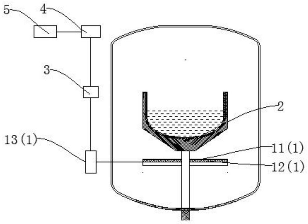
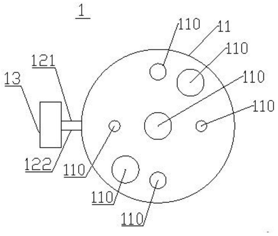
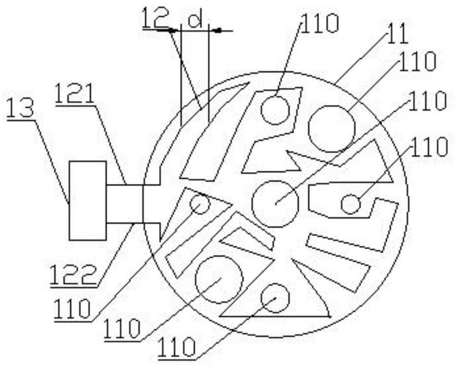
[0052] use figure 1 In the crystal growth furnace, a crucible 3 carrying solution is installed in the crystal growth furnace, and a bottom protection plate (not marked in the figure) is arranged under the crucible. The silicon leakage detection device 1 is arranged on the bottom protection pressure plate, and the detection line follows image 3 The non-uniform circuit layout shown (without cladding material layer), the detection line should avoid the thermal field components during the layout process (2 electrodes of the main heater, 2 electrodes of the side heater, 2 exhaust hole, 1 supporting rod), the distance d between the adjacent line segments of the detection line is 5-15mm (d value is not fixed), the detection unit 13 is connected with the incoming line end 121 and the outgoing line end 122 of the detection line 12, and the detection line The resistance value, and the judgment of silicon leakage is carried out through the change of the resistance value. The detection u...
Embodiment 2
[0054] The difference with Embodiment 1 is that the silicon leakage detection device includes a cladding material layer 11, and the cladding material layer 11 has a thermal field member (two electrodes of the main heater, side 2 electrodes of the heater, 2 exhaust holes, 7 through holes 110 of 1 supporting rod), detection line 12 is arranged in the middle of cladding material layer 11, and cladding material layer is quartz fiber cloth, and its aperture is 6 μm, the thickness of a single layer is 0.03mm, the upper layer of the coating material layer is 10 layers, the lower layer of the central area of the coating material layer is 100 layers, and the lower layer at the edge area of the coating material layer is 0-20mm. It is 150 floors.
Embodiment 3
[0056] The difference from Example 2 is that the cladding material layer is quartz fiber cloth with a pore size of 2 μm and a single layer thickness of 0.05 mm. The upper layer of the cladding material layer is 8 layers, and the central area of the cladding material layer is The lower layer is 50 layers, and the lower layer at the 20mm edge region of the cladding material layer is set to 70 layers.
PUM
| Property | Measurement | Unit |
|---|---|---|
| Aperture | aaaaa | aaaaa |
| Thickness | aaaaa | aaaaa |
| Aperture | aaaaa | aaaaa |
Abstract
Description
Claims
Application Information