Mining drilling machine

A technology for drilling rigs and mines. It is applied in the direction of rotary drilling rigs, drill pipes, and drill pipes. It can solve problems such as high work intensity, potential safety hazards, and low efficiency. It can reduce labor intensity, adjust relative distances, and prevent high-temperature damage. Effect

Pending Publication Date: 2021-09-17
浙江杰亚机械制造有限公司
View PDF0 Cites 0 Cited by
  • Summary
  • Abstract
  • Description
  • Claims
  • Application Information

AI Technical Summary

Problems solved by technology

With the mining of coal in mines year by year, the mining depth is gradually increasing. In recent years, with the increase of mining depth, there have been more and more roadway floor heaving phenomena. After the roadway floor heaving is deformed, the cross section is reduced, which affects transportation, ventilation and personnel walking. Conducive to mine safety production
The bottom drum is a technical problem that needs to be solved in coal mining. The commonly used bottom drum deformation control method is mainly to implement floor grouting reinforcement. Reinforcement and reconstruction generally use mining drilling rigs to drill holes in roadways with large cross-sections. However, the existing mining drilling rigs still have the following shortcomings during construction. The required manual workload is large, the work intensity is high, the efficiency is low, and there are great safety hazards; 2. The existing mining drilling rigs are in harsh environments such as the fuselage cannot be rotated in the narrow mine tunnel, obstacles are blocked, and ditches are restricted. Work normally under working conditions; 3. It is impossible to cool the drill pipe that heats up during work in time

Method used


Image

  • Mining drilling machine
  • Mining drilling machine
  • Mining drilling machine

Examples


Embodiment Construction

[0023] The following will clearly and completely describe the technical solutions in the embodiments of the present invention with reference to the accompanying drawings in the embodiments of the present invention. Obviously, the described embodiments are only some, not all, embodiments of the present invention. Based on the embodiments of the present invention, all other embodiments obtained by persons of ordinary skill in the art without creative efforts fall within the protection scope of the present invention.

[0024] Each embodiment of the present invention can specifically refer to the description shown in the description Figure 1-Figure 5 .

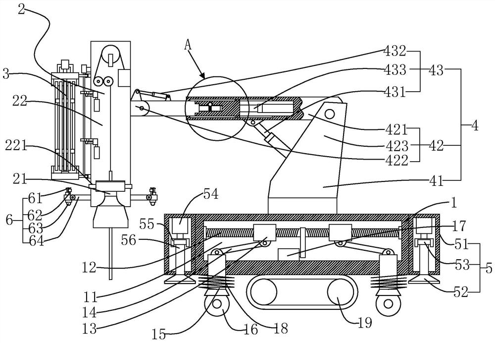
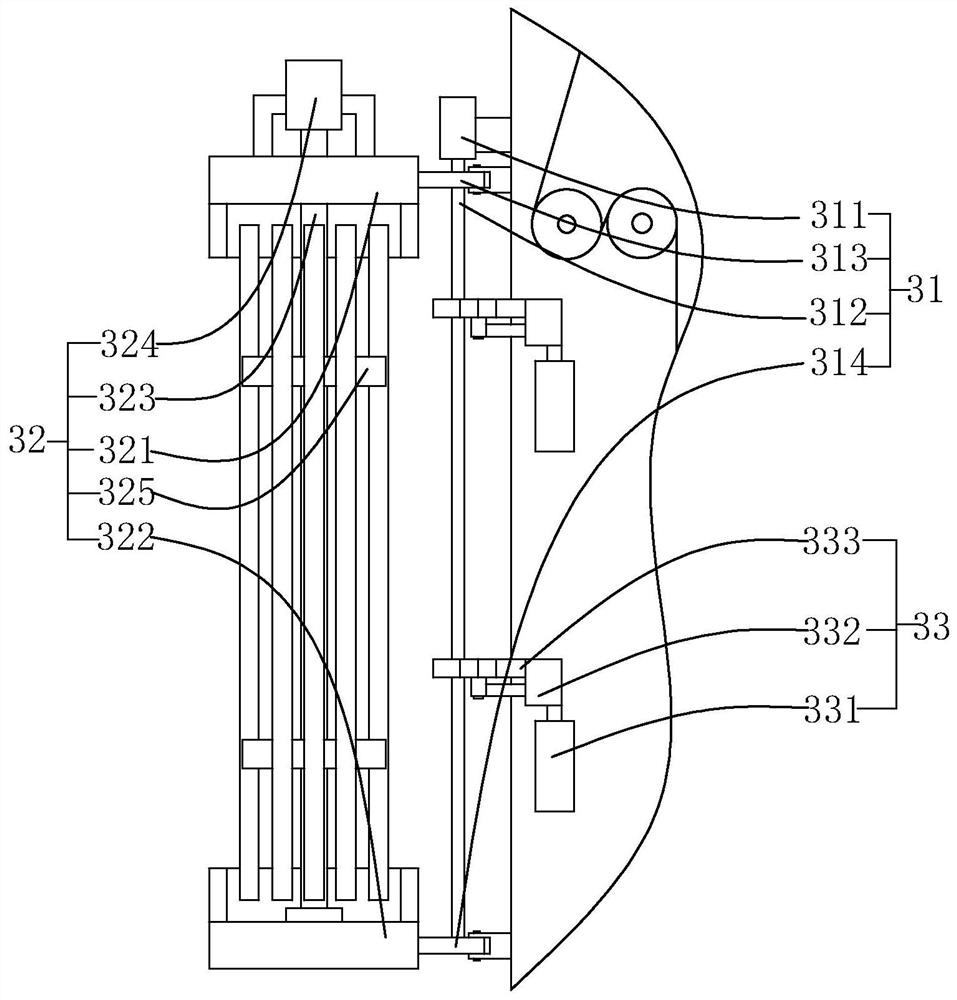
[0025] The invention discloses a drilling rig for mining, which comprises a drilling rig platform 1 and a drilling rig 2 arranged on the drilling rig platform 1. The drilling rig 2 is provided with a power head 21 and a guide rail for guiding the power head 21 to move in a straight line. 22. The guide rail 22 is provided with a ...


PUM


Abstract

The invention relates to the field of mining machinery, in particular to a mining drilling machine. The mining drilling machine comprises a drilling machine platform and a drilling machine body arranged on the drilling machine platform, a power head and a guide rail used for guiding the power head to move linearly are arranged on the drilling machine body, and a clamping seat used for clamping a drilling rod is arranged on the guide rail. The mining drilling machine is characterized in that an automatic rod replacing device and an aerial fog mechanism are arranged on the guide rail of the drilling machine body, an adjusting mechanism used for controlling the drilling machine body to execute corresponding actions is installed on the drilling machine platform, and the end, away from the drilling machine platform, of the adjusting mechanism is connected with the guide rail. The provided drilling machine has the functions of automatically changing rods, cooling and dedusting, the position of the drilling machine is adjusted more conveniently, and adaptability is higher.

Description

technical field [0001] The invention relates to the field of mining machinery, in particular to a mining drilling rig. Background technique [0002] In coal production engineering, a large number of roadways need to be excavated. In order to reduce the cost of roadway excavation and improve the stability of surrounding rock, it is necessary to reinforce the rocks around the roadway. With the mining of coal in mines year by year, the mining depth is gradually increasing. In recent years, with the increase of mining depth, there have been more and more roadway floor heaves. After the roadway floor heave is deformed, the cross section is reduced, which affects transportation, ventilation and personnel walking. Conducive to mine safety production. The floor drum is a technical problem that needs to be solved in coal mining. The commonly used method of controlling the deformation of the floor drum is mainly to implement floor grouting reinforcement. Reinforcement and reconstruc...

Claims


Application Information

Patent Timeline
Patent Type & Authority Applications(China)
IPC IPC(8): E21B7/02E21B15/00E21B19/18E21B19/14E21B19/086E21B3/02E21B21/16
CPCE21B7/022E21B15/00E21B19/18E21B19/14E21B19/086E21B3/02E21B21/16
Inventor 柴宁杰马云青胡李元康靖祝峰斌
Owner 浙江杰亚机械制造有限公司
Why Eureka
Try Eureka