
Phase change waste heat recovery, ventilation and heating system for shower room

A waste heat recovery and heating system technology, applied in heating systems, space heating and ventilation, space heating and ventilation details, etc., can solve problems such as heat waste, large heat loss, and complicated processes, so as to reduce energy consumption, Improve the comfort of heating, the effect of comfortable ventilation and heating

Pending Publication Date: 2021-09-17
CHINA UNITED NORTHWEST INST FOR ENG DESIGN & RES
View PDF0 Cites 0 Cited by
  • Summary
  • Abstract
  • Description
  • Claims
  • Application Information

AI Technical Summary

Problems solved by technology

[0003] Shower is a common way of bathing in people's daily life. When taking a bath, the water is poured all over the body with a nozzle. If the drainage channel goes away, the large amount of heat still remaining in the wastewater will also be drained away, thus causing a waste of energy
At the same time, the shower room is full of high-temperature water vapor with high temperature during showering, and the direct discharge also causes waste of heat.
[0004] The existing shower room waste heat recovery system collects waste water and uses it as preheating of shower water through heat exchange. This kind of waste heat recovery has little effect, and the heat loss during heat exchange is large, and the process is complicated; at the same time, the water temperature and radiation of shower waste water The water temperature requirements for heating are similar, and the shower room has heating requirements when showering

Method used


Image

  • Phase change waste heat recovery, ventilation and heating system for shower room
  • Phase change waste heat recovery, ventilation and heating system for shower room

Examples


Embodiment Construction

[0037] The following will clearly and completely describe the technical solutions in the embodiments of the present invention with reference to the accompanying drawings in the embodiments of the present invention. Obviously, the described embodiments are some of the embodiments of the present invention, but not all of them. Based on the embodiments of the present invention, all other embodiments obtained by persons of ordinary skill in the art without making creative efforts belong to the protection scope of the present invention.

[0038]In describing the present invention, it should be understood that the terms "center", "longitudinal", "transverse", "upper", "lower", "front", "rear", "left", "right", " The orientation or positional relationship indicated by "vertical", "horizontal", "top", "bottom", "inner", "outer", "side", "end", "side" etc. is based on the Orientation or positional relationship is only for the convenience of describing the present invention and simplify...


PUM

PropertyMeasurementUnit
Phase transition temperatureaaaaaaaaaa

Abstract

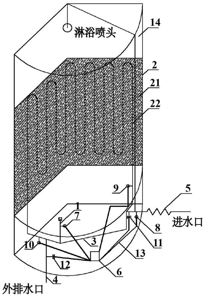
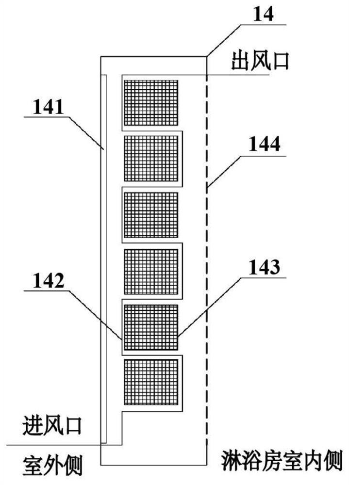
The invention discloses a phase change waste heat recovery, ventilation and heating system for a shower room. A heating water pipe mesh grid is embedded in the bottom area of the shower room and the 2 / 3 area, close to the bottom, of a peripheral wall plate; a hot water circulating pipeline inlet of the heating water pipe mesh grid is connected with an inner water outlet of the shower room through a first connecting pipeline; the first connecting pipeline is connected with a shower hot water supply pipeline of a water inlet of the shower room through a second connecting pipeline, the first connecting pipeline and the second connecting pipeline are both connected with the initial end of a snakelike coil pipe in the heating water pipe mesh grid, and the tail end of the snakelike coil pipe is connected with an outer water outlet of the shower room through a third connecting pipeline; the first connecting pipeline, the second connecting pipeline and the snakelike coil pipe are respectively connected with a micro intelligent analysis controller, so that the temperature and flow control of hot water in the pipelines can be realized; a phase change waste heat recovery and ventilation wall plate is embedded in the 1 / 3 area, close to the top, of the peripheral wall plate of the shower room. The energy-saving and comfortable ventilation and heating effects in the shower room can be achieved.

Description

technical field [0001] The invention belongs to the technical fields of energy saving and phase change, and in particular relates to a phase change waste heat recovery ventilation and heating system for a shower room. Background technique [0002] The shower room is easy to install, highly mobile, and highly convenient. It is a popular bathroom choice with dry and wet separation and strong installation independence no matter in urban or rural areas. [0003] Shower is a common way of bathing in people's daily life. When taking a bath, the water is poured all over the body with a nozzle. If the waste water is drained, the large amount of heat still remaining in the waste water will also be drained away, thus causing a waste of energy. At the same time, the shower room is full of high-temperature water vapor with higher temperature during showering, and direct discharge also causes waste of heat. [0004] The existing shower room waste heat recovery system collects waste wat...

Claims


Application Information

Patent Timeline
IPC IPC(8): F24D19/00F24D19/10F28D20/02F24H3/02F24H9/18
CPCF24D19/0002F24D19/1006F28D20/021F24H3/02F24H9/1854Y02E60/14
Inventor 田伟唐振宇党硕张迪柴悦田进杨肖虎郭俊菲
Owner CHINA UNITED NORTHWEST INST FOR ENG DESIGN & RES
Learn More