Ion beam three-dimensional dose distribution detection device and method

A three-dimensional dose and detection device technology, used in dosimeters, X-ray/γ-ray/particle irradiation therapy, radiotherapy, etc. Achieve fast and accurate verification, improved efficiency and accuracy, and lightweight equipment

Pending Publication Date: 2021-09-17
INST OF MODERN PHYSICS CHINESE ACADEMY OF SCI
View PDF18 Cites 0 Cited by
  • Summary
  • Abstract
  • Description
  • Claims
  • Application Information

AI Technical Summary

Problems solved by technology

This method has high precision, but the disadvantage is that it can only measure the dose of one point at a time, and it takes a long time to obtain a complete dose distribution, and the efficiency is low
The film measurement method is also widely used, and can directly measure the dose distribution in the horizontal and vertical directions. The disadvantage is that it cannot be reused and the cost is high. Manual positioning is required, and there are positioning errors, and post-processing takes a long time.
The two-dimensional ion chamber matrix is ​​usually used in the measurement of lateral dose distribution. The advantage is that it is easy to set up and the measurement speed is fast. The disadvantage is that the resolution is low and the longitudinal dose distribution cannot be measured.
The depth dose distribution detector is used to measure the longitudinal dose distribution. The advantage is that it can quickly obtain a complete longitudinal dose distribution curve. The disadvantage is that it measures the integrated dose and cannot reflect the dose distribution curve of the beam in the transverse direction.
The scintillator detector utilizes the characteristics of the interaction between the beam and the fluorescent target to detect the light signal through the camera and convert it into a dose distribution, so as to realize fast dose distribution detection. The advantages are fast speed, high resolution, and easy to use. Currently, only In the measurement of the transverse two-dimensional dose distribution, the measurement of the three-dimensional dose distribution cannot be carried out
Therefore, the current dose distribution detection method has not been able to achieve the ideal state in terms of detection accuracy, efficiency, and convenience.

Method used


Image

  • Ion beam three-dimensional dose distribution detection device and method
  • Ion beam three-dimensional dose distribution detection device and method
  • Ion beam three-dimensional dose distribution detection device and method

Examples


Embodiment 1

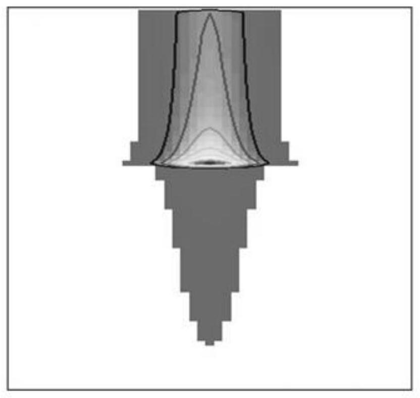
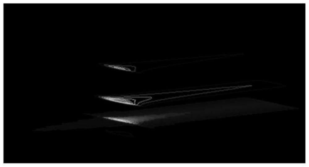
[0053] Fig. 2(a) shows the two-dimensional cross-sectional structure of a position in the transverse direction of the beam spot in the depth direction obtained by using the dose distribution detection device of the present invention. It can be seen that the structure information of the irradiation field in the depth direction can be accurately obtained by using the detection device of the present invention, so that some basic information of the beam spot can be obtained, such as the size distribution of the beam spot at different positions in the depth direction. Fig. 2(b) is the three-dimensional dose distribution of the beam spot obtained after three-dimensional reconstruction. Figure 3(a) shows the two-dimensional cross-sectional structure of a fault in the depth direction under a regular irradiation field. The two-dimensional dose distribution of the irradiation field can be quickly obtained by using the device of the invention. Figure 3(b) is the three-dimensional dose d...


PUM


Abstract

The invention relates to an ion beam three-dimensional dose distribution detection device and method. The ion beam three-dimensional dose distribution detection device comprises a luminescent material, a position moving device, an optical image acquisition unit and an image processing unit, wherein the position moving device is fixedly provided with the luminescent material and is used for gradually translating the luminescent material in the vertical beam direction according to a preset measurement position track, a to-be-detected ion beam enters along the direction vertical to the thickness of the luminescent material and interacts with the luminescent material to generate fluorescence, the optical image acquisition unit is used for measuring the generated fluorescence in real time, and sending a measured cross section image, containing the two-dimensional dose distribution of the to-be-detected ion beam, of the luminescent material to the image processing unit, and the image processing unit is used for obtaining three-dimensional dose distribution of the to-be-detected ion beam according to the measured cross section image of the luminescent material and the preset measurement position track. The device can be widely applied to the technical field of ion beam measurement.

Description

technical field [0001] The invention belongs to the technical field of ion beam radiotherapy, and in particular relates to an ion beam three-dimensional dose distribution detection device and method. Background technique [0002] In ion beam radiation therapy: firstly, the patient's three-dimensional anatomical structure information is obtained through CT scanning; secondly, the tumor target area and surrounding organs at risk are delineated in the CT image; thirdly, a reasonable irradiation field direction is designed and the irradiation parameters are adjusted. Through optimization, the three-dimensional dose distribution of the target area and organs at risk is obtained; finally, the irradiation parameters verified by the plan are sent to the accelerator control system to achieve precise irradiation of the tumor target area. It can be seen that the realization of radiotherapy involves many links, and problems in each link will have an impact on the final treatment effect....

Claims


Application Information

Patent Timeline
Patent Type & Authority Applications(China)
IPC IPC(8): G01T1/02A61N5/10
CPCG01T1/02A61N5/1071A61N2005/1087
Inventor 贺鹏博李强陈卫强唐凯车宇航康宇杰
Owner INST OF MODERN PHYSICS CHINESE ACADEMY OF SCI
Why Eureka
Try Eureka