Rotary cut guide wire and calcification lesion tearing device

A technology of guide wire and cutting parts, which is applied in the field of vascular calcification treatment equipment, can solve the problems of insufficient cutting force and easily scratched blood vessels by the balloon, and achieve high safety results

Active Publication Date: 2021-09-21
HARBIN MEDICAL UNIVERSITY +1
View PDF7 Cites 2 Cited by
  • Summary
  • Abstract
  • Description
  • Claims
  • Application Information

AI Technical Summary

Problems solved by technology

[0005] In order to solve the problem in the prior art that the cutting force of the spinous process balloon and the double guide wire balloon is not enough, and the cutting balloon is easy to scratch the blood vessel, one of the purposes of the present invention is to provide a rotary cutting guide wire

Method used


Image

  • Rotary cut guide wire and calcification lesion tearing device
  • Rotary cut guide wire and calcification lesion tearing device
  • Rotary cut guide wire and calcification lesion tearing device

Examples


Embodiment 1

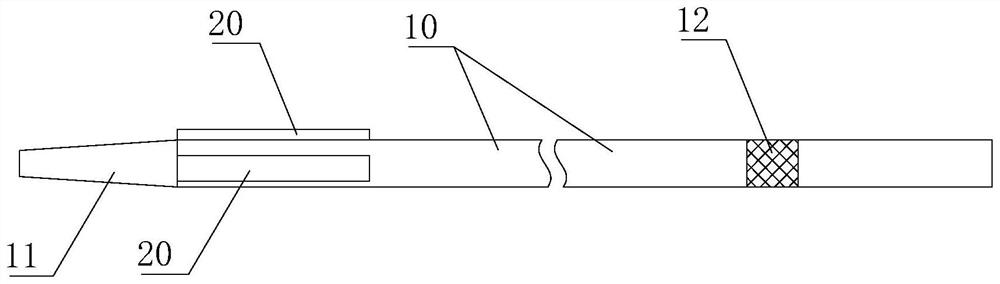
[0041] Please also refer to Figure 1 to Figure 4 , the present embodiment provides a rotary cutting guide wire, which is used to divide the calcified lesion, so that the medical staff can smoothly expand the stent in the lesion area and perform the operation. The rotary cutting guide wire includes a guide wire body 10 , a plurality of cutting parts 20 and at least one sticking part 30 , and the cutting parts 20 and the sticking parts 30 are both directly or indirectly arranged on the guide wire body 10 .

[0042] Specifically, the outer edge of the cross section of the guide wire body 10 is circular.

[0043] Furthermore, for the lesion area, since the inner wall of the blood vessel is attached with calcified lesion, the inner diameter of the place is obviously smaller than the inner diameter of the normal area of ​​the blood vessel. In order to enable the guide wire body 10 to smoothly penetrate into the lesion area, a guide part 11 is provided at one end of the guide wire ...

Embodiment 2

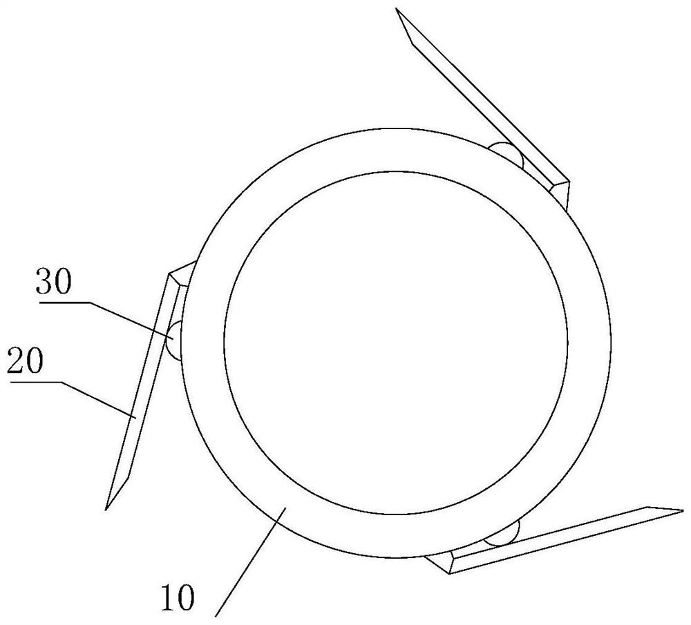
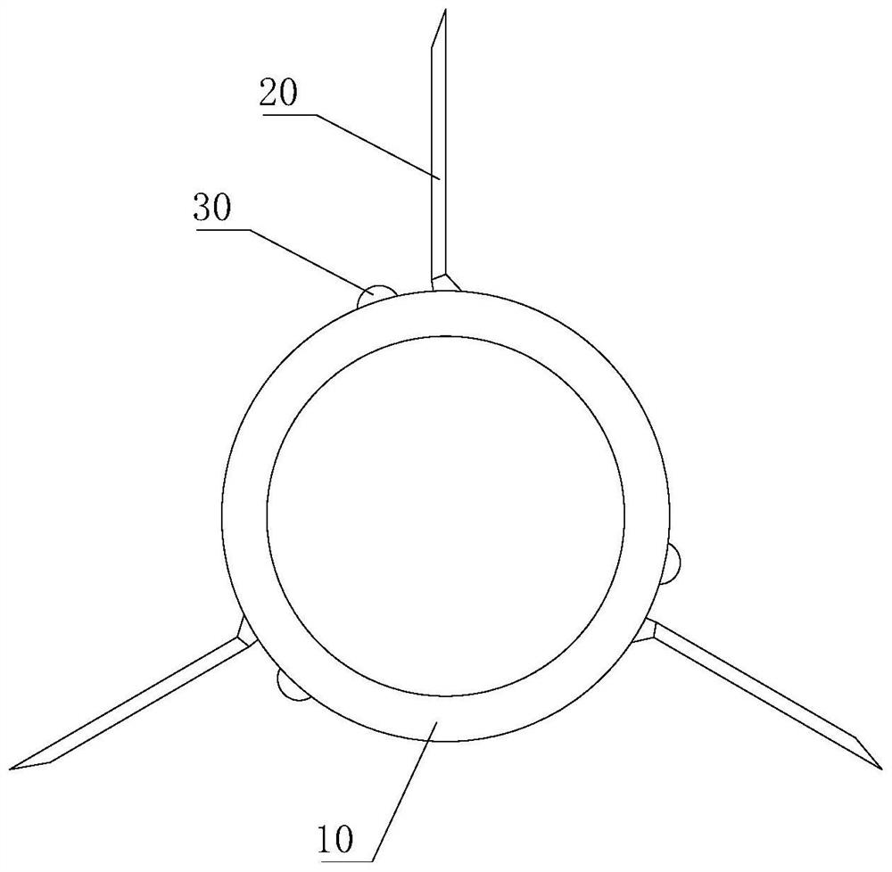
[0067] Please also refer to Figure 5 with Image 6 , and the difference from Embodiment 1 is that each cutting member 20 is connected to the guide wire body 10 through a sticking part 30, and the sticking part 30 adopts an elastic block.

[0068] Specifically, the elastic block can be made of silica gel, rubber and other materials, and the cutting part 20 is glued to the guide wire body 10 through the elastic block. The elastic block can also be made of spring steel, the cutting part 20 is welded and fixed with the elastic block, and the elastic block is welded and fixed with the guide wire body 10 .

[0069] In particular, when the elastic block keeps its original shape, the cutting member 20 is tangent to the guide wire body 10 and is gathered on the surface of the guide wire body 10 .

[0070] After the medical personnel use the guide wire body 10 to transport the cutting piece 20 to the calcified lesion, the cutting edge of the cutting piece 20 collides with the inner e...


PUM


Abstract

The invention provides a rotary cut guide wire and a calcification lesion tearing device. The rotary cut guide wire comprises a guide wire body, a plurality of cutting pieces and at least one attaching piece, wherein the cutting pieces and the attaching piece are arranged on the guide wire body. The multiple cutting pieces are arranged in the circumferential direction of the guide wire body, one side of each cutting piece is rotationally connected with the guide wire body, the other side of each cutting piece is provided with a cutting edge, and the cutting edges are away from the guide wire body when the cutting pieces rotate relative to the guide wire body. The attaching piece enables multiple cutting pieces to be gathered on the surface of the guide wire body, the cutting pieces are not prone to scratching blood vessels when entering the blood vessels along with the guide wire body, and safety is high. A medical worker conveys the cutting pieces to the calcification lesion position through the guide wire body, then the guide wire body is further rotated, the side, connected to the guide wire body, of the cutting pieces is driven to rotate, and the cutting edges of the cutting pieces are blocked by the calcification lesion and do not rotate along with the guide wire body. The cutting pieces overcome the acting force of the attaching piece and rotates relative to the guide wire body, the cutting pieces are gradually unfolded from the folded state, and the cutting edges are gradually away from the guide wire body and cut into the calcification lesion.

Description

technical field [0001] The invention relates to the field of vascular calcification treatment equipment, in particular to a rotary cutting guide wire and a tearing device for calcified lesions. Background technique [0002] Percutaneous coronary intervention (PCI) is the most important means of treating coronary heart disease. However, in the treatment of calcified lesions, because the calcified lesions are very hard, it is difficult for ordinary balloons to expand the lesion area, which makes it difficult for medical staff to expand the stent smoothly and support the narrow lesions, making the operation very difficult. [0003] At this time, some special balloons are needed to dilate the lesion first, such as spinous process balloons, double guide wire balloons, and cutting balloons. The spinous process balloon is a few small protrusions of polymer materials glued on the surface of the balloon. When the balloon is inflated, the small protrusions are relatively hard, thereb...

Claims


Application Information

Patent Timeline
Patent Type & Authority Applications(China)
IPC IPC(8): A61B17/3207
CPCA61B17/320725A61B17/320758A61B2017/320741
Inventor 于波齐大鹏候静波张东会
Owner HARBIN MEDICAL UNIVERSITY
Why Eureka
Try Eureka