
GPS receiver autonomous integrity monitoring method

A GPS receiver and integrity monitoring technology, applied in the field of satellite navigation receivers, can solve the problems of easily falling into local optimum, affecting the accuracy of PF estimation, particle depletion, etc., so as to improve the problem of particle depletion and improve particle diversity. The effect of stability and fast convergence speed

Pending Publication Date: 2021-09-21
中航机载系统共性技术有限公司
View PDF0 Cites 0 Cited by
  • Summary
  • Abstract
  • Description
  • Claims
  • Application Information

AI Technical Summary

Problems solved by technology

[0003] The research on the GPSRAIM method mainly focuses on fault detection and isolation (fault detection and isolation, FDI) technology based on redundant information. The related algorithms include pseudorange comparison method, least square residual method, parity vector method, etc. Efficient detection of small faults
In addition, the traditional Kalman filter can only deal with the Gaussian system well, otherwise the fault estimation performance will be degraded, and the signal, noise and interference in the GPS receiver system are not standard Gaussian distribution, only using the traditional Kalman filter will affect the accuracy of RAIM sex
In response to this problem, although the RAIM algorithm based on the particle filter (Particle filter, PF) and log likelihood ratio consistency test was proposed, using the suboptimal estimation ability of PF for non-Gaussian and nonlinear systems, PF itself has some Defects, such as particle degradation and particle depletion issues, seriously affect the estimation accuracy of PF
Although there are many RAIM-related works to improve PF, such as particle swarm optimization (PSO) and chaotic particle swarm optimization to improve PF particles, the PSO algorithm also has problems such as slow convergence speed and easy to fall into local optimum.

Method used


Image

  • GPS receiver autonomous integrity monitoring method
  • GPS receiver autonomous integrity monitoring method
  • GPS receiver autonomous integrity monitoring method

Examples


Embodiment Construction

[0094] Embodiments of the technical solutions of the present invention will be described in detail below in conjunction with the accompanying drawings. The following examples are only used to illustrate the technical solution of the present invention more clearly, so they are only examples, and should not be used to limit the protection scope of the present invention.

[0095] It should be noted that, unless otherwise specified, the technical terms or scientific terms used in this application shall have the usual meanings understood by those skilled in the art to which the present invention belongs.

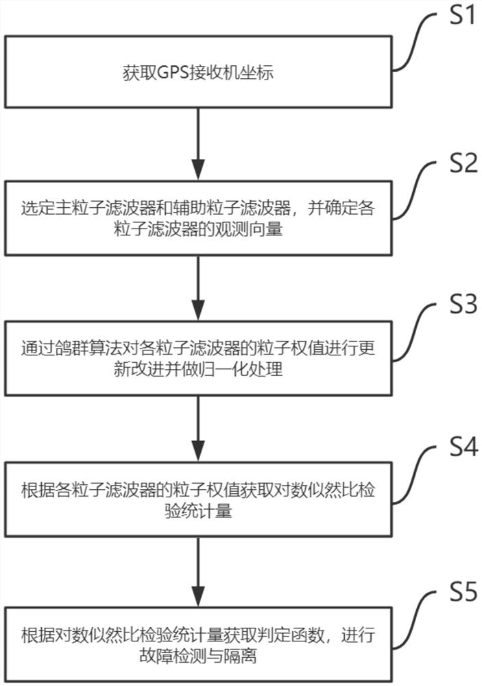
[0096] figure 1 For a flow chart of the steps of a GPS receiver autonomous integrity monitoring method provided in an embodiment of the present invention, see figure 1 , the method includes the following steps:

[0097] S1: Calculate the coordinates of the GPS receiver by receiving signals from several satellites.

[0098] Select n=6 GPS satellites, numbered 3, 8, 12, 24, 26, ...


PUM


Abstract

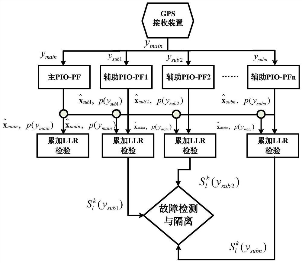
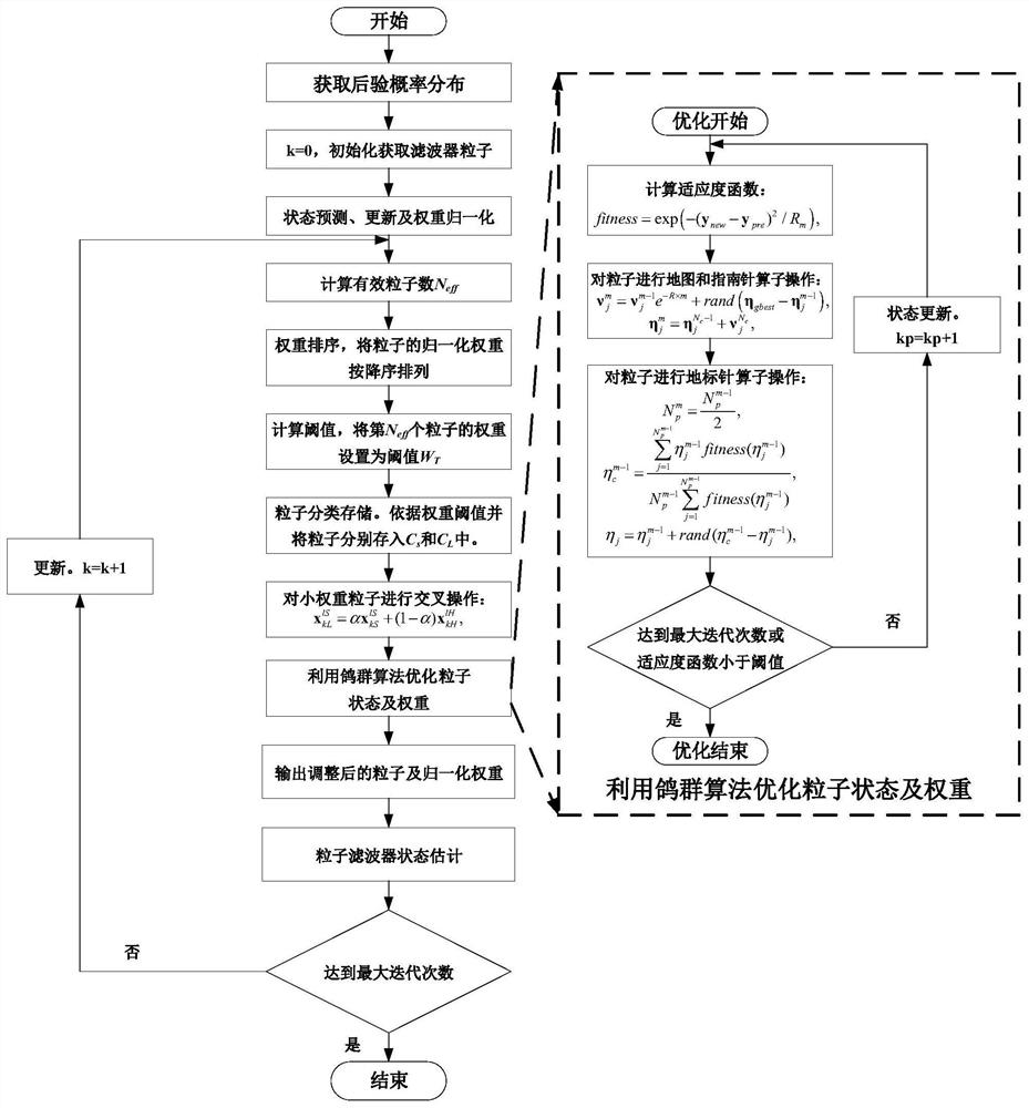
The invention belongs to the technical field of satellite navigation receivers, and provides a GPS receiver autonomous integrity monitoring method, which comprises the following steps: S1, acquiring coordinates of a GPS receiver; S2, selecting a main particle filter and an auxiliary particle filter, and determining an observation vector of each particle filter; S3, updating, improving and normalizing the particle weight of each particle filter through a pigeon inspired algorithm; S4, obtaining a log-likelihood ratio test statistic according to the particle weight of each particle filter; and S5, obtaining a judgment function according to the log-likelihood ratio test statistics, and carrying out fault detection and isolation. According to the method, PF particles are optimized and adjusted through the pigeon inspired algorithm, so that the number of effective particles is increased, the diversity of the particles is improved, and the problem of particle depletion is solved.

Description

technical field [0001] The invention relates to the technical field of satellite navigation receivers, in particular to a GPS receiver autonomous integrity monitoring method. Background technique [0002] GPS is the most widely used global satellite navigation system in the world today, and it has been successfully used in navigation equipment and track recording equipment of various vehicles such as aviation, marine and land vehicles. For global satellite positioning and navigation systems represented by GPS, especially in navigation systems with very high reliability requirements such as airborne electronic navigation equipment, integrity testing is an indispensable link in the development of related systems. The research on Receiver Autonomous Integrity Monitoring (RAIM) method based on the consistency check of redundant ranging information has become the current GPS fault diagnosis and alarm and integrity method because of its advantages of rapid response, simple impleme...

Claims


Application Information

Patent Timeline
IPC IPC(8): G01S19/23
CPCG01S19/23
Inventor 田川牟明王闯陆敏敏于沛许政郭强
Owner 中航机载系统共性技术有限公司
Learn More