
Thermal imaging equipment

A technology of thermal imaging and equipment, applied in the field of thermal imaging, can solve problems such as interference with external infrared rays, heating of components, and unsatisfactory interference effects of thermal imaging cores.

Active Publication Date: 2021-09-21
ZHEJIANG DAHUA TECH
View PDF13 Cites 1 Cited by
  • Summary
  • Abstract
  • Description
  • Claims
  • Application Information

AI Technical Summary

Problems solved by technology

The study found that the higher the temperature, the stronger the infrared radiation emitted by the object, and the components on the internal circuit board of the device in the working state will heat up, which will interfere with the external infrared received by the thermal imaging core and affect the accuracy of imaging.
[0003] Most of the uncooled thermal imaging cores in the existing technology are methods to enhance the heat dissipation of components on the internal circuit board of the equipment. The above methods reduce the temperature of the components, but cause the internal temperature of the equipment where the thermal imaging core is located to rise. The effect of reducing interference with the thermal imaging core is not ideal

Method used


Image

  • Thermal imaging equipment
  • Thermal imaging equipment
  • Thermal imaging equipment

Examples


Embodiment Construction

[0023] The following will clearly and completely describe the technical solutions in the embodiments of the present invention with reference to the accompanying drawings in the embodiments of the present invention. Obviously, the described embodiments are only some, not all, embodiments of the present invention. Based on the embodiments of the present invention, all other embodiments obtained by persons of ordinary skill in the art without making creative efforts belong to the protection scope of the present invention.

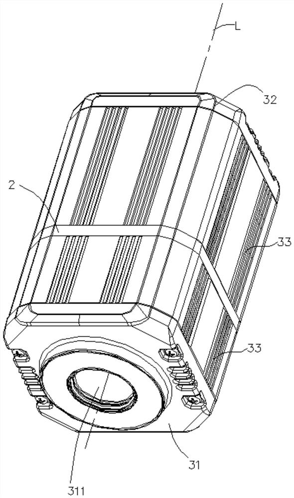
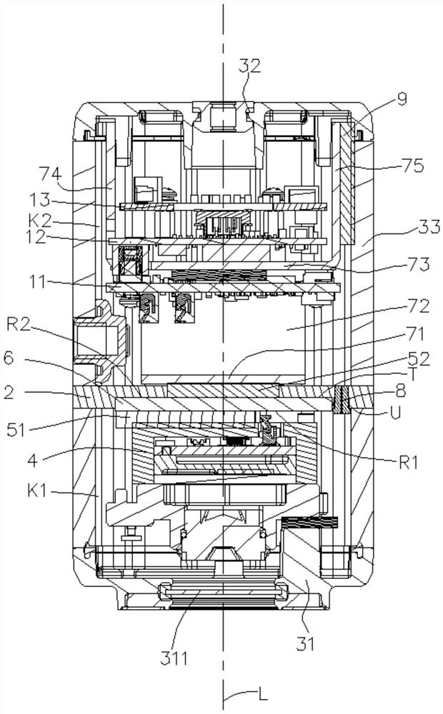
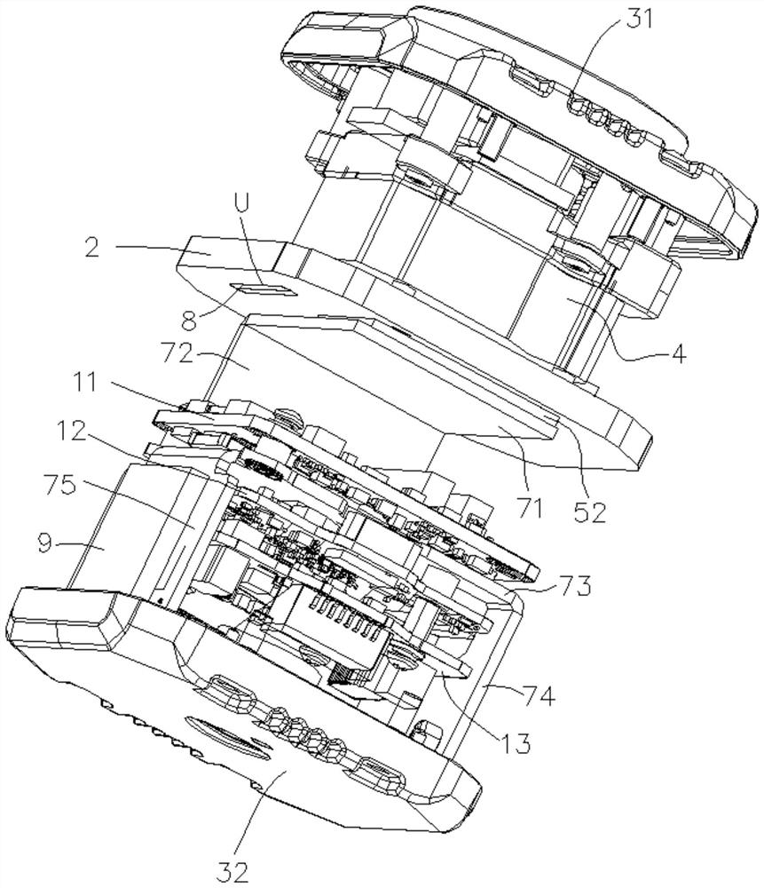
[0024] combine Figure 1 to Figure 6 :

[0025] The thermal imaging device provided by the embodiment of the present application includes: a housing, a thermal insulation layer 2, a wire, a thermal imaging core 4, a refrigerator 6, a heat conduction bracket 7 and a circuit board; the housing includes a top plate 31, a bottom plate 32 and a surrounding wall 33 The above-mentioned parts of the housing are made of metal materials with good heat dissipation effec...


PUM


Abstract

The invention relates to the technical field of thermal imaging, and discloses thermal imaging equipment. The thermal imaging equipment comprises a shell, a thermal insulation layer, a thermal imaging machine core and a circuit board. The thermal insulation layer divides the inner space defined by the shell into a first cavity and a second cavity. The thermal imaging machine core is arranged in the first cavity, and the circuit board is arranged in the second cavity. The thermal insulation layer divides the closed space defined by the shell into the first cavity and the second cavity which are independent of each other, and the thermal insulation layer can block heat convection of the first cavity and the second cavity, so the first cavity and the second cavity are prevented from heat exchange through air at least to a certain extent. The thermal imaging machine core is arranged in the first cavity, and the circuit board is arranged in the second cavity, so that heat emitted by components on the circuit board is not prone to be conducting to the first cavity through the thermal insulation layer, the temperature rise effect of the components on the circuit board on the environment of the second cavity where the thermal imaging machine core is located is reduced, and the influence on the thermal imaging effect of the thermal imaging machine core is reduced.

Description

technical field [0001] The invention relates to the technical field of thermal imaging, in particular to a thermal imaging device. Background technique [0002] With the rapid development of science and technology, people have explored nature more and more deeply, and gradually discovered a variety of electromagnetic waves, especially infrared rays. Studies have found that substances with a temperature higher than the absolute temperature will produce infrared rays. Therefore, infrared rays are an excellent medium for detecting objects in nature, and thermal imaging equipment can be used for imaging through the infrared radiation emitted by the target itself. It is used in national defense security, industrial temperature measurement and civilian use And other fields are more and more widely used, especially the non-refrigerated thermal imaging core is greatly superior to the air compression refrigeration with high cost, large volume and slow start due to its advantages of l...

Claims


Application Information

Patent Timeline
IPC IPC(8): H05K7/02H05K7/20F25B21/02H04N5/33
CPCH05K7/02H05K7/20F25B21/02H05K7/2039H04N5/33
Inventor 黄恒敏王潇楠温跃明卢伍平刘振
Owner ZHEJIANG DAHUA TECH
Learn More