Water-air amphibious multi-rotor unmanned aerial vehicle

A multi-rotor unmanned aerial vehicle, water and air technology, applied in the field of unmanned aerial vehicles, can solve the problem that unmanned aerial vehicles do not have amphibious ability, etc., and achieve the effect of improving the passing ability, facilitating transportation and transfer, and reducing the volume

Pending Publication Date: 2021-09-24
FUDAN UNIV
View PDF0 Cites 1 Cited by
  • Summary
  • Abstract
  • Description
  • Claims
  • Application Information

AI Technical Summary

Problems solved by technology

[0004] Aiming at the problem that the UAVs in the prior art do not have amphibious capabilities, the purpose of the present invention is to provide a water-air amphibious multi-rotor UAV

Method used


Image

  • Water-air amphibious multi-rotor unmanned aerial vehicle
  • Water-air amphibious multi-rotor unmanned aerial vehicle
  • Water-air amphibious multi-rotor unmanned aerial vehicle

Examples


Embodiment 1

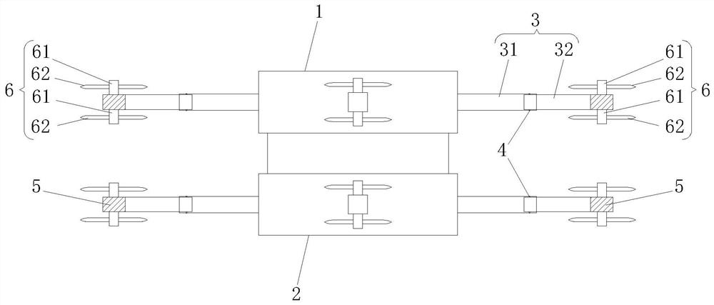
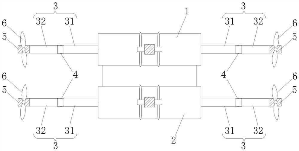
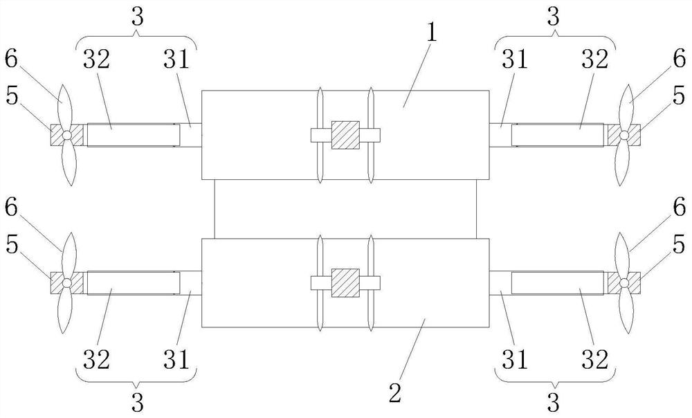
[0024] A water-air amphibious multi-rotor UAV, such as Figure 1-3 As shown, it includes an upper fuselage 1 and a lower fuselage 2 that are stacked and fixed, wherein the upper fuselage 1 and the lower fuselage 2 are rectangular structures, and each includes four side walls, and the side walls of the two are in the up and down direction. After the upper pair, the respective top and bottom surfaces are fixedly connected by connecting members, such as plates or rods.

[0025] Wherein, the upper fuselage 1 and the lower fuselage 2 are center-symmetrically or evenly arranged with a plurality of arms 3 , and the arms 3 are all lockable telescopic arms. In this embodiment, four machine arms 3 are installed on the upper fuselage 1 and the lower fuselage 2, and for any one of the upper fuselage 1 and the lower fuselage 2, the four machine arms 3 are respectively installed on On its 4 side walls, so that the 4 machine arms 3 are symmetrically arranged in the center and evenly arrange...

Embodiment 2

[0033]The difference from the first embodiment is that the rotor assembly 6 includes double-layered blades 62 . For example, the rotor assembly 6 includes two motors 61 , the two motors 61 are coaxially and symmetrically arranged on both sides of the tilting base 5 , and a blade 62 is installed on the output shaft of each motor 61 . When in use, by adjusting the rotational speed and direction of the two motors 61, the two blades 62 can be coaxially reversed, thereby forming a coaxially reversed propeller, so that the drone has a higher hovering efficiency, and has a more Low induced resistance, at the same time, the maneuverability of the UAV is increased, and can ensure relatively good stability.


PUM


Abstract

The invention discloses a water-air amphibious multi-rotor unmanned aerial vehicle, and belongs to the field of unmanned aerial vehicles, the water-air amphibious multi-rotor unmanned aerial vehicle comprises an upper fuselage and a lower fuselage which are stacked and fixed, the upper fuselage and the lower fuselage are each provided with a plurality of vehicle arms which are centrally symmetrically or circumferentially and uniformly arranged, and the vehicle arms are all telescopic vehicle arms which can be locked; the tip of each vehicle arm is rotatably connected with a tilting base and fixedly provided with a tilting steering engine for driving the tilting base to rotate, and the rotating axis of the tilting base is parallel to the vehicle arm; each tilting base is provided with a rotor assembly, each rotor assembly comprises a motor and a paddle installed on the output shaft of the motor, and the output shaft of each motor is perpendicular to the rotating axis of the corresponding tilting base. The unmanned aerial vehicle is simple in structure and reasonable in design, not only can sail in the air, on the water surface and underwater, but also can improve the transportation capacity and the trafficability in narrow terrains by shortening the vehicle arms.

Description

technical field [0001] The invention relates to the technical field of unmanned aerial vehicles, in particular to a water-air amphibious multi-rotor unmanned aerial vehicle. Background technique [0002] Unmanned aircraft, referred to as "unmanned aerial vehicle", or "UAV" in English, is an aircraft that is controlled by radio remote control equipment and its own program control device, or is completely or intermittently operated autonomously by an onboard computer. UAVs are currently used in a wide range of fields, and are widely used in military and civilian applications. In terms of military use, UAVs are divided into reconnaissance aircraft and target aircraft. In terms of civil use, UAVs are currently widely used in aerial photography, agriculture, plant protection, miniature selfies, express delivery, disaster relief, observation of wild animals, monitoring of infectious diseases, surveying and mapping, news reports, power inspections, film and television shooting, et...

Claims


Application Information

Patent Timeline
Patent Type & Authority Applications(China)
IPC IPC(8): B64C35/00B60F5/02B64C1/06B64C1/30
CPCB64C35/008B64C35/005B60F5/02B64C1/063B64C1/30
Inventor 张立艾剑良
Owner FUDAN UNIV
Why Eureka
Try Eureka