Buffer device with leg type structure

A cushioning device and leg-type technology, applied in the field of robotics, can solve the problem that the aircraft cannot be attached stably, and achieve the effect of simple structure, simple method and high efficiency

Pending Publication Date: 2021-09-28
SHANGHAI UNIV
View PDF0 Cites 0 Cited by
  • Summary
  • Abstract
  • Description
  • Claims
  • Application Information

AI Technical Summary

Problems solved by technology

The space vehicle will generate a large impulse when it moves at high speed, which makes the vehicle generate huge instantaneous energy when it comes into contact with the spacecraft in a gravity-free space environment, causing the vehicle to be quickly bounced off, making the vehicle unable to attach stably to the space vehicle. on the spacecraft

Method used


Image

  • Buffer device with leg type structure
  • Buffer device with leg type structure
  • Buffer device with leg type structure

Examples


Embodiment 1

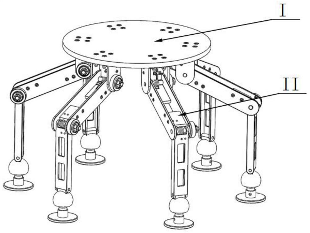
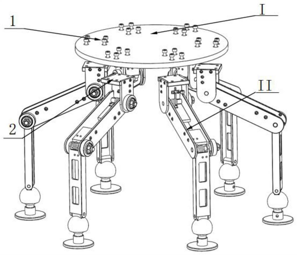
[0038] In this example, see figure 1, a buffer device with a leg-type structure, including a device placement plate I and a plurality of buffer energy-absorbing legs II, the buffer energy-absorbing legs II have a connecting plate 2 connected to the device placement plate I through a bolt 1; each The buffer energy-absorbing leg II has multiple joints, and each joint has a torsion spring 7; when the buffer device collides with the target surface, the angle of each joint of the buffer energy-absorbing leg II changes, so that the torsion spring 7 located at the joint When deformation occurs, the kinetic energy is converted into elastic potential energy, and the joint can only rotate in one direction, so as to avoid the conversion of elastic potential energy into kinetic energy and cause rebound movement, resulting in buffer failure; the buffer device adopts a multi-leg configuration, which can adapt to the complex surface characteristics of the target , improve stability and buffe...

Embodiment 2

[0041] This embodiment is basically the same as Embodiment 1, especially in that:

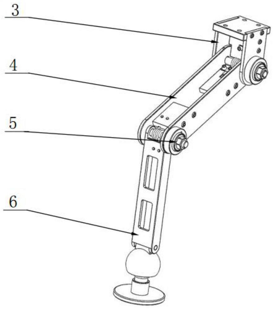
[0042] In this embodiment, the buffer energy-absorbing leg II includes an upper support leg 3, a middle support leg 4, a lower support leg 6 and a one-way energy-absorbing structure 5. There are two groups of one-way buffer structures 5, and the upper support leg 3 One group between the middle support legs 4, one group between the middle support legs 4 and the lower support legs 6.

[0043] In this embodiment, the upper support leg 3 is connected with the device placement plate 1 through the connecting plate 2, the connecting plate 2 is in a concave shape, and is fixedly connected with the two side plates 16 by bolts 8, and the upper supporting leg 3 Place plate 1 vertically to device, the connecting hole of energy-absorbing mechanism is set on both side plates 16; Be fixed with torsion spring fixed plate 15 with side plate 16 perpendicular positions, one side of torsion spring 7 is fixed on to...

Embodiment 3

[0050] This embodiment is basically the same as the above-mentioned embodiment, and the special features are:

[0051] In this embodiment, the ball pair 21 has three degrees of freedom, and its movement space is a cone with a cone angle of 15°, constituting a buffer structure.

[0052] In this embodiment, the stiffness coefficient of the torsion spring 7 located at the joint of the middle support leg 4 and the lower support leg 6 is smaller than the stiffness coefficient of the torsion spring 7 at the joint of the upper support leg 3 and the middle support leg 4, realizing two joints Simultaneously act to form a device for absorbing and storing energy.

[0053] In this embodiment, before the initial contact, the angle formed by the center line of the upper support leg 3 and the center line of the middle support leg 4, the angle formed by the center line of the middle support leg 4 and the center line of the lower support leg 6, Both are 120°, and the state of each buffer leg ...


PUM


Abstract

The invention relates to a buffering device with a leg type structure. The buffering device comprises a device containing plate and a plurality of buffering energy-absorbing legs. According to the technology, the physiological structure and jumping characteristics of locust legs are used for reference, the contact rebound phenomenon between an aircraft and a target spacecraft is avoided, and kinetic energy is absorbed and converted into elastic potential energy to dissipate impact energy during collision contact. Therefore, the device can adapt to complex surface characteristics, has high efficiency, can effectively solve the key problems of smooth contact and stable landing of small aircrafts. In the invention, the six buffer energy-absorbing legs are uniformly distributed in the circumferential direction of a device placing plate (I); wherein the buffering and energy-absorbing legs achieve buffering and shock absorption through torsional springs and one-way bearings, rebound is avoided.The six-leg structure is adopted to increase the buffering load capacity, the buffering device can meet the requirement for non-forward collision contact buffering, and on the basis, the feet connected through the ball pairs have multiple degrees of freedom and can adapt to the irregular surface of a target object. The buffer device has universality and can provide application prospects and reference for buffering and shock absorption in other fields.

Description

technical field [0001] The invention relates to a buffer device with a leg structure, which belongs to the field of robots. Background technique [0002] With the profound development of China's space technology, deep space exploration and space station construction are progressing steadily, and more aircraft and probes will be sent to space. The safe interaction between aircraft and the stable landing of probes are the key factors for spacecraft to perform space operations. , The premise of improving efficiency. In the field of space robots, how to stably attach high-speed flying vehicles to spacecraft has high scientific research value. The space vehicle will generate a large impulse when it moves at high speed, which makes the vehicle generate huge instantaneous energy when it comes into contact with the spacecraft in a gravity-free space environment, causing the vehicle to be quickly bounced off, making the vehicle unable to attach stably to the space vehicle. on the s...

Claims


Application Information

Patent Timeline
IPC IPC(8): B62D57/032B64G1/16
CPCB62D57/032B64G1/16
Inventor 汪田鸿金滔李龙田应仲
Owner SHANGHAI UNIV
Why Eureka
Try Eureka