
Method and device for measuring straightness of pipe end of steel pipe

A measurement method and technology of a measurement device, applied in the direction of measurement devices, optical devices, instruments, etc., can solve problems such as long measurement time, unsatisfactory measurement results, and deviation of measurement results, so as to facilitate monitoring, improve measurement efficiency and accuracy, and accurately measured effect

Active Publication Date: 2021-09-28
BAOSHAN IRON & STEEL CO LTD
View PDF15 Cites 1 Cited by
  • Summary
  • Abstract
  • Description
  • Claims
  • Application Information

AI Technical Summary

Problems solved by technology

There are many problems in manual measurement: such as arbitrariness and large errors, long measurement time, etc.
There are two problems in this measurement method: one is that the middle area of ​​the steel pipe 1.5 meters away from the pipe end is considered to be completely straight, and there will be a certain degree of curvature in this area in actual production, which will cause the measurement results to deviate from the real situation ; The second is to take the outermost part of the pipe end as the position of the maximum deviation
In actual measurement, there may be non-unidirectional bending at the end of the steel pipe, such as C-type, S-type bending, etc., so the 0 meter place at the end of the pipe is not the maximum bending position. Therefore, the measurement of the straightness of the end of the steel pipe in the prior art The method cannot reflect the true straightness of the steel pipe, nor can it meet the needs of modern steel pipe production.

Method used


Image

  • Method and device for measuring straightness of pipe end of steel pipe
  • Method and device for measuring straightness of pipe end of steel pipe
  • Method and device for measuring straightness of pipe end of steel pipe

Examples


Embodiment 1

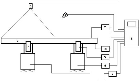
[0066] Pipe 2 levels detected to be placed on a measuring station, in place of the detector 9 detects the steel pipe 2 reaches the station, the system starts. Direct calculation unit 8 processes the signal via the interface unit 7 and the collecting pipe size standards on the detection of the current test station data, and data obtained by the pipe diameter and other dimensions of the diameter measuring device 10 measures, and in accordance with the outer diameter of the steel pipe 2 and detecting rotational angular velocity corresponding to the standard is calculated, the controller 6 to control the rotational driving of the steel pipe 2 at a constant rotational angular velocity w. Due to different specifications of the outer diameter of the steel pipe 2, in order to ensure the consistency and accuracy of measurement, it is necessary to ensure uniform measurement points distributed in the circumferential direction, i.e., equal to the angle θ between the two measurement points, wi...


PUM


Abstract

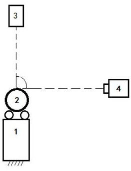
The invention discloses a method and a device for measuring straightness of a pipe end of a steel pipe. The device comprises a laser (3), an industrial camera (4), an angle sensor (5), a rotation controller (6) and a straightness calculation unit (8); the laser is arranged right above the steel pipe and projects strip-shaped laser to the surface of the steel pipe to form a light strip curve, and the steel pipe is controlled by the rotation controller to rotate all around during measurement. According to the method, the industrial camera collects thecontour image of a light band curve and sends the contour image to the straightness calculation unit, the angle sensor collects the current angle of the steel pipe and sends the current angle to the straightness calculation unit, the straightness calculation unit calculates single straightness values, and the maximum value of all the single straightness values is the straightness value of the pipe end; according to the invention, the curve parameters are extracted through the light band curve formed by irradiating the surface of the steel pipe with the laser to calculate the straightness of the pipe end of the steel pipe, and more accurate measurement is realized by setting 360-degree all-round rotation, so that the measurement efficiency and precision of the straightness of the pipe end are improved, and the quality monitoring of the steel pipe is facilitated.

Description

Technical field [0001] The present invention relates to a steel tube mass detecting device and method, and more particularly to a method and apparatus for a non-contact steel pipe end degrees. Background technique [0002] Steel tubes are one of the important products of steel enterprises, with a wide range of applications in various industrial sectors such as chemical, metallurgy, and machinery. For steel pipe products, the straightness is an important indicator for measuring the quality of steel pipes. Collisions, temperature changes during production, processing, self-weighing, etc., can cause steel tube plastic deformation, resulting in steel pipe spherical requirements that cannot be satisfied, so that the requirements for continuous improvement of steel pipe products are increasing. Usually the tube is a steel pipe processing, a common portion of the connection, is also the largest part of the degree error, according to the US Petroleum Society (API) on the cannula and tubi...

Claims


Application Information

Patent Timeline
Patent Type & Authority Applications(China)
IPC IPC(8): G01B11/27G01B11/24G01B21/10
CPCG01B11/27G01B11/24G01B21/10
Inventor 申屠理锋张建伟胡继康余勇左宏志谢麒麟奚嘉奇
Owner BAOSHAN IRON & STEEL CO LTD
Learn More