Laser

A technology of lasers and light-emitting components, which is applied in the field of lasers, can solve the problems of poor surface flatness, easy deformation, and affecting the light output effect of the laser, so as to reduce internal stress, reduce the probability of deformation, and ensure the effect of light output

Active Publication Date: 2021-09-28
QINGDAO HISENSE LASER DISPLAY CO LTD
View PDF10 Cites 3 Cited by
  • Summary
  • Abstract
  • Description
  • Claims
  • Application Information

AI Technical Summary

Problems solved by technology

[0004] However, in the related art, if the fixing reliability of the conductive pins of the light-emitting component is to be improved, it is necessary to make the conductive pins have a sufficient contact area with the opening of the frame, thereby increasing the wall thickness of the frame. The bottom plate is

Method used


Image

  • Laser
  • Laser
  • Laser

Examples


Embodiment Construction

[0021] In order to make the purpose, technical solution and advantages of the present application clearer, the implementation manners of the present application will be further described in detail below in conjunction with the accompanying drawings.

[0022] With the development of optoelectronic technology, lasers are used more and more widely. For example, lasers can be used as light sources in laser projection or laser TV. The following embodiments of the present application provide a laser, which can improve the sealing performance of openings in the frame of the laser, and improve the manufacturing effect and quality of the laser.

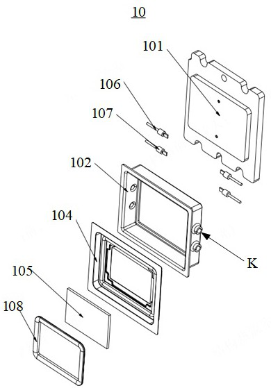
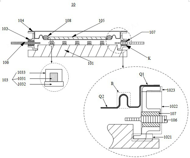
[0023] figure 2 It is a schematic diagram of an exploded structure of a laser provided in an embodiment of the present application, image 3 It is a schematic structural diagram of a laser provided in the embodiment of this application. image 3 can be figure 2 Schematic representation of the cross-section a-a' of the laser shown. Please...


PUM

PropertyMeasurementUnit
Thicknessaaaaaaaaaa
Wall thicknessaaaaaaaaaa

Abstract

The invention discloses a laser, and belongs to the technical field of photoelectricity. The laser comprises a bottom plate, a frame body, a plurality of light-emitting assemblies, a cover plate and a light-transmitting sealing layer; the frame body is arranged on the bottom plate in a surrounding mode and forms a containing space, and the light-emitting assemblies are all located in the containing space and fixed to the bottom plate; the frame body is in a thin plate shape, the upper portion of the frame body is folded outwards to form a first folded edge, and the first folded edge is fixed to the outer edge area of the cover plate; the light-transmitting sealing layer is fixed with the inner edge area of the cover plate and covers the opening of the cover plate; and the lower portion of the frame body is folded inwards or outwards to form a second folded edge, and the second folded edge is fixedly connected with the bottom plate. The assembly difficulty of the laser can be reduced, and the light emitting effect of the laser can be ensured.

Description

technical field [0001] This application relates to the field of optoelectronic technology, in particular to a laser. Background technique [0002] With the development of optoelectronic technology, lasers are widely used. [0003] figure 1 It is a structural schematic diagram of a laser provided by the related art. Such as figure 1 As shown, the laser 00 includes a bottom plate 001 , an annular frame 002 , a plurality of light emitting components 003 , a cover plate 004 , a light-transmitting sealing layer 005 and a plurality of conductive pins 006 . Wherein, the frame body 002 and the light emitting components 003 are both fixed on the bottom plate 001, and the frame body 002 surrounds the plurality of light emitting components 003. The cover plate 004 is an annular sheet metal part, the outer edge of the cover plate 004 is welded to the surface of the frame body 002 away from the bottom plate 001, and the edge of the light-transmitting sealing layer 005 is fixed to the...

Claims


Application Information

Patent Timeline
IPC IPC(8): H01S5/02216H01S5/02218H01S5/40
CPCH01S5/02216H01S5/02218H01S5/4025
Inventor 李建军
Owner QINGDAO HISENSE LASER DISPLAY CO LTD
Why Eureka
Try Eureka