Envelope detection circuit based on Schmitt circuit and working method thereof

A circuit and wave envelope technology, which is applied in the field of AM wave demodulation circuit, can solve the problems such as the inability to effectively reflect the changing law of the envelope and the inability to realize AM wave demodulation, etc., and achieve the effect of simplified structure, rapid pulse inversion and stable performance.

Inactive Publication Date: 2021-09-28
SHANDONG UNIV
View PDF7 Cites 0 Cited by
  • Summary
  • Abstract
  • Description
  • Claims
  • Application Information

AI Technical Summary

Problems solved by technology

[0004] The traditional Schmidt circuit scheme has no emitter-to-ground capacitance, and cannot effectively reflect the changing law of its envelope when dealing with high-frequency AM waves. It can only detect high-frequency carrier waves, and cannot directly demodulate AM waves.

Method used


Image

  • Envelope detection circuit based on Schmitt circuit and working method thereof
  • Envelope detection circuit based on Schmitt circuit and working method thereof
  • Envelope detection circuit based on Schmitt circuit and working method thereof

Examples


Embodiment 1

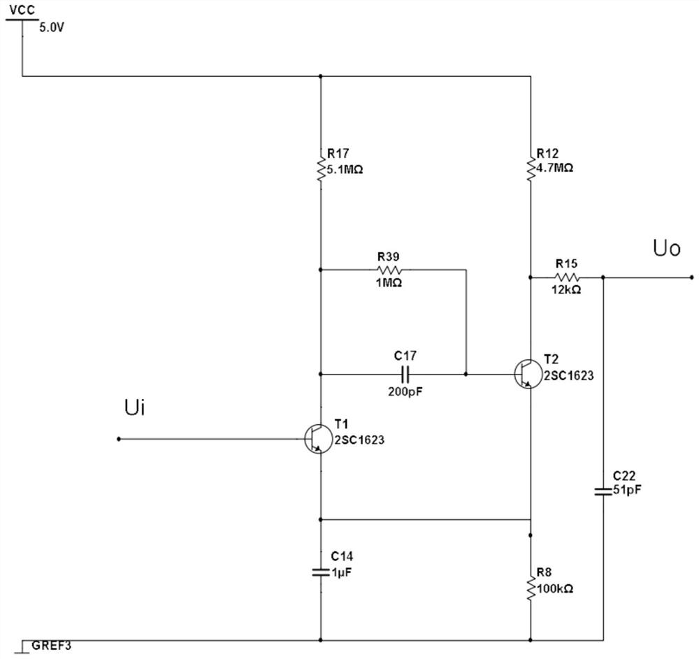
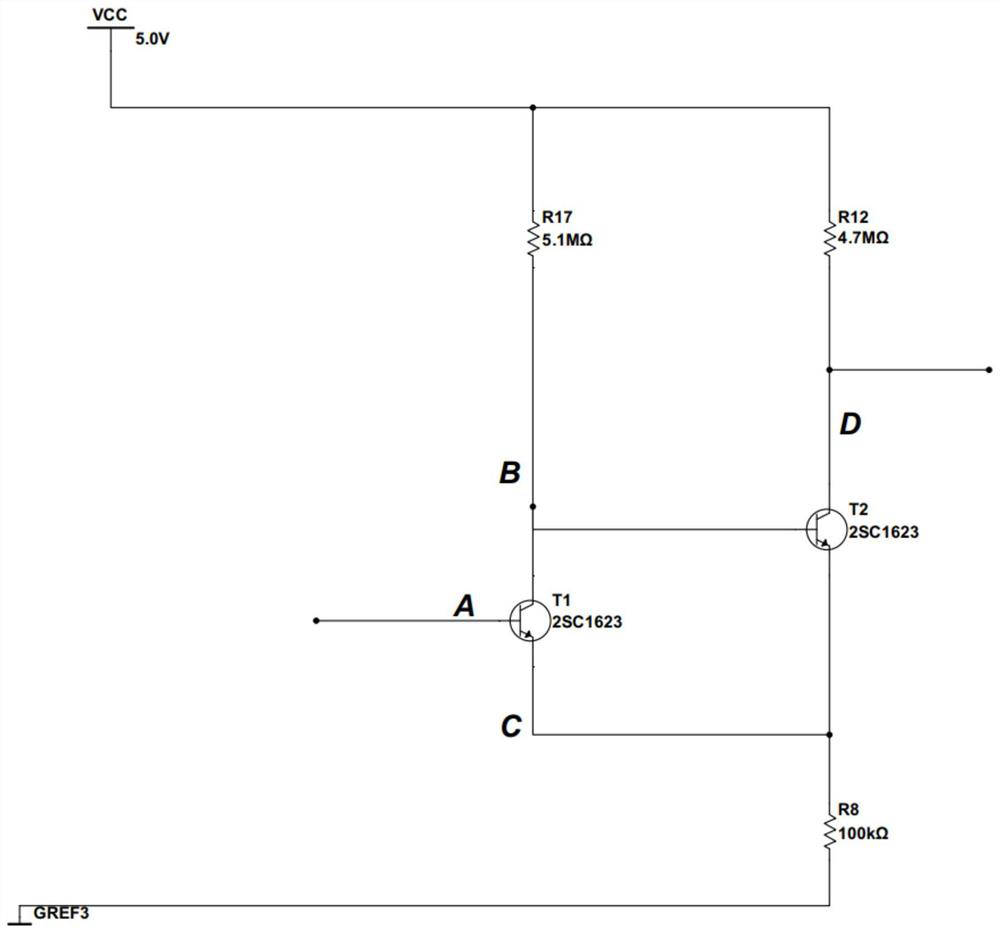
[0031] A kind of envelope detection circuit based on Schmidt circuit, such as figure 1 As shown, it includes two cascaded identical NPN transistors, three capacitors, and five resistors; two cascaded identical NPN transistors include a first transistor T1, a second transistor T2, and three The capacitor includes the first capacitor C14, the second capacitor C17, and the third capacitor C22, and the five resistors include the first resistor R8, the second resistor R17, the third resistor R12, the fourth resistor R39, and the fifth resistor R15;

[0032] The first capacitor C14 is connected in parallel with the first resistor R8; the second capacitor C17 is connected in parallel with the fourth resistor R39; the third capacitor C22 is connected in series with the fifth resistor R15; The collector of the first triode T1 is connected to the base of the second triode T2, the emitter of the first triode T1 is connected to the emitter of the second triode T2; one end of the first ca...

Embodiment 2

[0039] The working method of the envelope detection circuit based on the Schmidt circuit described in embodiment 1 comprises the steps as follows:

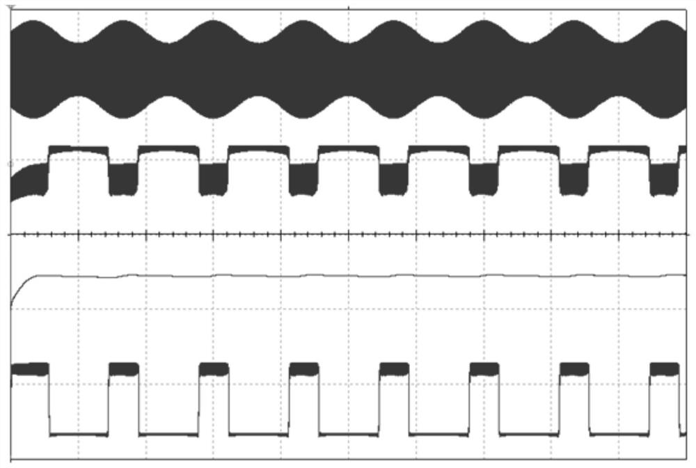
[0040] (1) The amplitude modulation wave is input from the base of the first triode T1 in the envelope detection circuit, and the first resistor R8 and The first capacitor C14 together forms an envelope detection circuit to perform peak envelope detection on the input AM wave, and the emitter of the first triode T1 outputs the AM wave envelope;

[0041] (2) The AM wave envelope passes through the reconstructed Schmidt circuit, and the amplitude of the AM wave envelope exceeds the upper limit flipping threshold V of the Schmidt circuit 1 , at about 0.65V, the state of the Schmitt circuit flips, and the second triode T 2 The collector output voltage jumps rapidly from low potential to high potential; when the amplitude of the amplitude modulation wave envelope is less than the lower limit flipping threshold V of the Schmidt circuit...


PUM


Abstract

The invention relates to an envelope detection circuit based on a Schmitt circuit and a working method thereof. A diode peak envelope detection circuit and an envelope amplitude discrimination circuit in amplitude modulated wave demodulation are combined into one, so that the envelope detection circuit is simpler in structure and stable in performance. The circuit is improved on the basis of a classical Schmitt circuit, and compared with the classical Schmitt circuit, the circuit of the invention has the advantages that a capacitor is added between emission electrodes of two triodes and the ground, so that the working mechanism of the Schmitt circuit is changed, and amplitude discrimination of each carrier cycle of an amplitude-modulated wave is changed into amplitude discrimination of only envelope of the amplitude-modulated wave. An acceleration capacitor is added between the two triodes, so that the pulse is turned over more quickly, and the waveform edge is more regular. An RC first-order low-pass filter is added to the rear end of the circuit, and high-frequency components in waveforms are removed.

Description

technical field [0001] The invention relates to the field of power electronics, in particular to an AM wave demodulation circuit based on a classic Schmidt circuit and a working method thereof. Background technique [0002] The most important feature of the Schmitt trigger is that it can shape a slowly changing input signal into a rectangular pulse with steep edges. It consists of a two-stage DC amplifier with the emitters of the two transistors connected together. The circuit has two stable states, and the mutual conversion of the two steady states depends on the magnitude of the input signal. When the input signal potential reaches the on-potential and remains greater than the on-potential, the circuit remains in a certain steady state; if the input When the signal potential drops to the off potential and remains lower than the off potential, the circuit flips rapidly and remains in another state. This circuit is often used for potential discrimination, amplitude discrimi...

Claims


Application Information

Patent Timeline
Patent Type & Authority Applications(China)
IPC IPC(8): H03D1/18
CPCH03D1/18
Inventor 陈涤马世铭
Owner SHANDONG UNIV
Why Eureka
Try Eureka