Notch type continuum robot based on crossed bent beam structure

A continuum and robot technology, applied in the direction of surgical robots, etc., can solve the problems of excessive driving force, complex structure size, excessive material strain, etc., and achieve the effect of small bending friction, large internal and external diameter ratio, and small number of parts

Active Publication Date: 2021-10-01
SHANGHAI JIAO TONG UNIV
View PDF17 Cites 0 Cited by
  • Summary
  • Abstract
  • Description
  • Claims
  • Application Information

AI Technical Summary

Problems solved by technology

However, the current incision-type continuum robots are often difficult to ensure a large range of motion and high stiffness at the same time. While improving a certain aspect of performance, it often leads to excessive material strain during bending, and the required driving force is too large or Problems such as complex s

Method used


Image

  • Notch type continuum robot based on crossed bent beam structure
  • Notch type continuum robot based on crossed bent beam structure
  • Notch type continuum robot based on crossed bent beam structure

Examples


Example Embodiment

[0051] Example 1

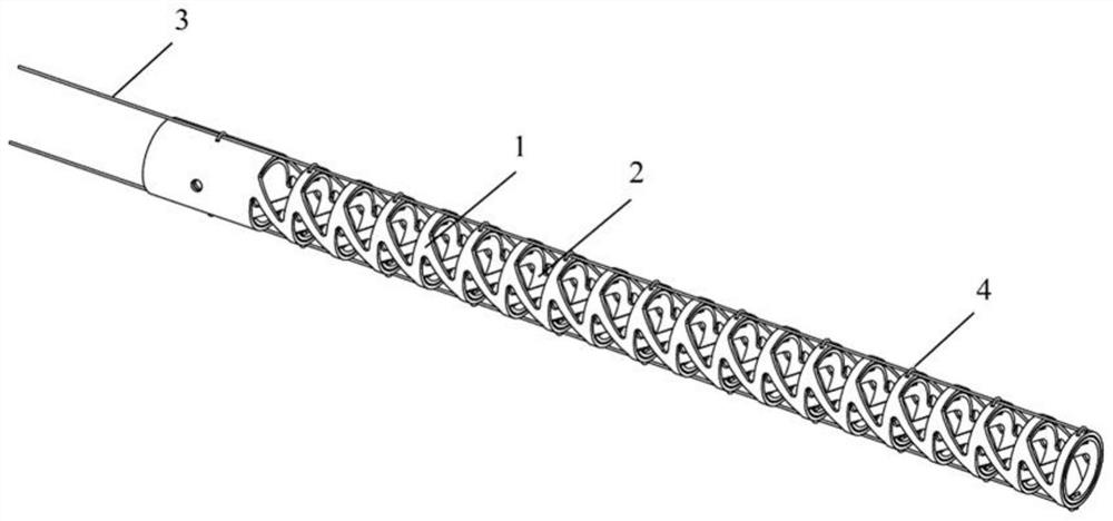
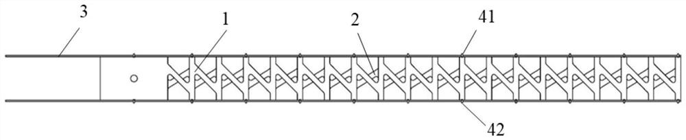
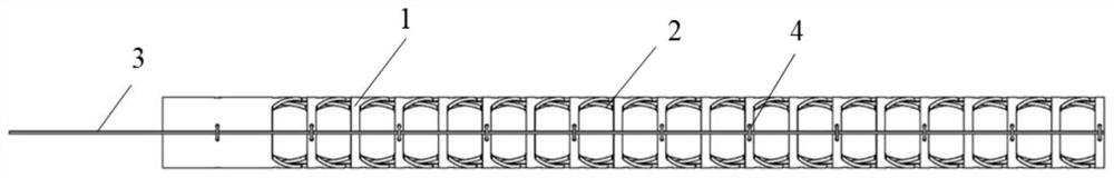
[0052] like Figure 1 to Figure 7 As shown, a notched continuum robot based on the cross-bending beam structure includes an outer tube notched skeleton 1, an inner tube notched skeleton 2 and a driving rope 3, and an inner tube notched skeleton 2 is sleeved inside the outer tube notched skeleton 1, and an outer notched skeleton 2 is provided. The side wall of the pipe incision skeleton 1 is provided with a driving rope channel 4, and one end of the driving rope 3 passes through the driving rope channel 4 and is fixedly connected with the top of the incision-type continuum robot. The outer tube notch frame 1 and the inner tube notch frame 2 are respectively processed from a nickel-titanium tube.

[0053] Outer tube otch skeleton 1 comprises nineteen exoskeleton bending joints 11 and an exoskeleton base 15, and interior tube incision skeleton 2 comprises nineteen inner skeleton bending joints 21 and an inner skeleton base 25; Outer skeleton bending joints 11 ...

Example Embodiment

[0059] Example 2

[0060] like Figure 8 to Figure 10 As shown, the main difference from Embodiment 1 is that the upper end surface and the lower end surface of the outer skeleton circular tube wall 13 and the inner skeleton circular tube wall are not perpendicular to the central axis of the continuum robot as a whole. The specific structure is as follows:

[0061] A notch-type continuum robot based on a cross-bending beam structure, comprising an outer tube notch frame 1, an inner tube notch frame 2 and a driving rope 3, an inner tube notch frame 2 is set inside the outer tube notch frame 1, and an outer tube notch frame The side wall of 1 is provided with a driving rope channel 4, and one end of the driving rope 3 passes through the driving rope channel 4 and is fixedly connected with the top of the incision-type continuum robot. The outer tube notch frame 1 and the inner tube notch frame 2 are respectively processed from a nickel-titanium tube.

[0062] Outer tube otch s...


PUM


Abstract

The invention provides a notch type continuum robot based on a cross bent beam structure. The robot comprises an outer pipe incision skeleton, an inner pipe incision skeleton and a driving rope, the inner pipe incision skeleton is sleeved in the outer pipe incision skeleton, and the side wall of the outer pipe incision skeleton is provided with a driving rope channel; one end of the driving rope penetrates through the driving rope channel and then is fixedly connected with the top end of the notch type continuum robot; the outer pipe notch framework comprises N outer framework bending joints and an outer framework base, and the inner pipe notch framework comprises N inner framework bending joints and an inner framework base; and the inclination directions of flexible micro beams in the outer skeleton bending joints and the inner skeleton bending joints are opposite. A laser cutting machining mode is adopted, the inner and outer pipe flexible notch frameworks with the crossed inclined micro beams is constructed, the inner and outer pipe frameworks are mutually nested to form the rope-driven continuum robot, and the rope-driven continuum robot has high rigidity and a large movement range.

Description

technical field [0001] The invention relates to the technical field of continuum robots, in particular to a notch-type continuum robot based on a cross-bending beam structure. Background technique [0002] At present, with the development of minimally invasive surgery, continuum robots are more and more widely used in the field of medical devices, especially in human cavity intervention and organ minimally invasive surgery. High, flexible and easy to control, compared with traditional rigid surgical instruments, it has great advantages. It can effectively reduce contact and collision with organs and tissues in the human body, reduce damage to the body and accurately locate the lesion. [0003] The incision-type continuum robot is a typical representative of flexible surgical robots. It cuts off certain materials by etching patterns on the outer wall of a rigid tube to form a single integral flexible instrument. Compared with the traditional hinged snake-bone continuum mecha...

Claims


Application Information

Patent Timeline
IPC IPC(8): A61B34/30
CPCA61B34/30A61B2034/302A61B2034/301
Inventor 陈卫东艾孝杰高安柱蔡易林
Owner SHANGHAI JIAO TONG UNIV
Why Eureka
Try Eureka