Micro catheter assembly

A technology of microcatheters and components, applied in the direction of catheters, hypodermic injection devices, etc., can solve the problems of poor flexibility and tightness, poor flexibility of microcatheters, easy deformation or bending, etc., so as to avoid bending or deformation and reduce surgical wounds , the effect of performance improvement

Pending Publication Date: 2021-10-01
四川艾迈思生物医疗科技股份有限公司
View PDF11 Cites 0 Cited by
  • Summary
  • Abstract
  • Description
  • Claims
  • Application Information

AI Technical Summary

Problems solved by technology

However, the existing microcatheter components are usually single-lumen catheters, and the drug solution is often in direct contact with the guide wire, and its drug effect is easily affected, and the microcatheter after being pushed into the blood vessel is less flexible, easily deformed or bent
[0003] The patent with the publication number CN103635222B discloses a microcatheter with a distal tip portion and a proximal solution lumen, and proposes a "slender tubular body with a proximal end of the main body, a distal end of the main body and a solution lumen", which can make the medicinal liquid and the catheter The filaments are in different chambers, but less flexible and tighter
[0004] The patent with the publication number CN109044484A discloses a catheter for manual thrombus suction, and proposes "a Y-shaped three-lumen tube that is hollow inside the injection seat, one end is the suction port, the other end is the injection port, and the other end is the working port; The working port is connected to the main pipe, and a stress relief member is provided at the junction of the working port and the main pipe; the end of the main pipe far away from the injection seat is connected to the tip tube, and the inside of the tip tube is provided with a guide wire cavity". In the suction chamber, the outer layer of the spring tube is used to improve the pushability and stretch resistance of the main tube, but the thrombus needs to be sucked out through negative pressure suction, and the operation is more complicated
[0005] Patent No. CN112169137A discloses an adjustable microcatheter for cerebrovascular intervention and its use method. It proposes to clamp the catheter body with structures such as applicators, cushions, ferrules, and splints to ensure the effectiveness of the catheter body and the ferrule. Fixed, that is, to achieve the positioning of the catheter body, but it needs to be operated by energizing the battery and the electromagnet. This operation requires circuit assembly, which is not very practical

Method used


Image

  • Micro catheter assembly
  • Micro catheter assembly
  • Micro catheter assembly

Examples


Embodiment 1

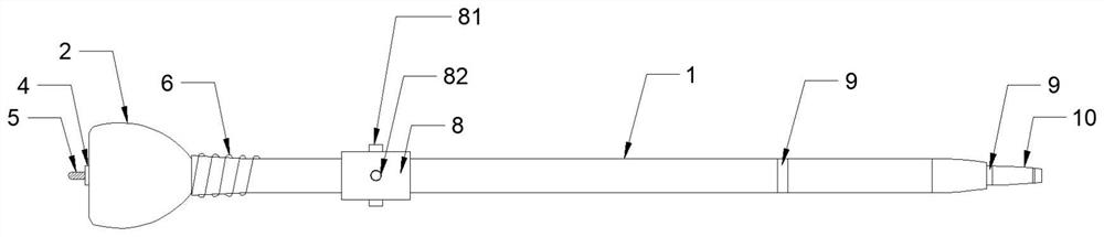
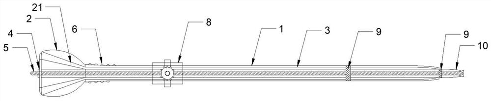
[0033] Such as Figure 1-2 As shown, a microcatheter assembly includes a tube body 1, wherein: the top of the tube body 1 is provided with a tube seat 2, and the inside of the tube body 1 includes an inner tube 3 and a lumen 4 arranged on the outer periphery of the inner tube 3, the tube The inside of the seat 2 is provided with a solution chamber 21 located outside the cavity tube 4, the cavity tube 4 is provided with a guide wire 5, and the connection between the tube base 2 and the tube body 1 is provided with an elastic wire 6, and the elastic wires 6 are all set for Elastic wire windings to avoid sudden stress changes in the tube body 1, the elastic wire 6 can effectively prevent the deformation of the microcatheter during advancement, and facilitate the multi-angle connection between the tube base 2 and the tube body 1 . The outer circumference of the tube body 1 is equipped with a ferrule 8 for fixing the microcatheter at a set position. The ferrule 8 includes a stop ri...

Embodiment 2

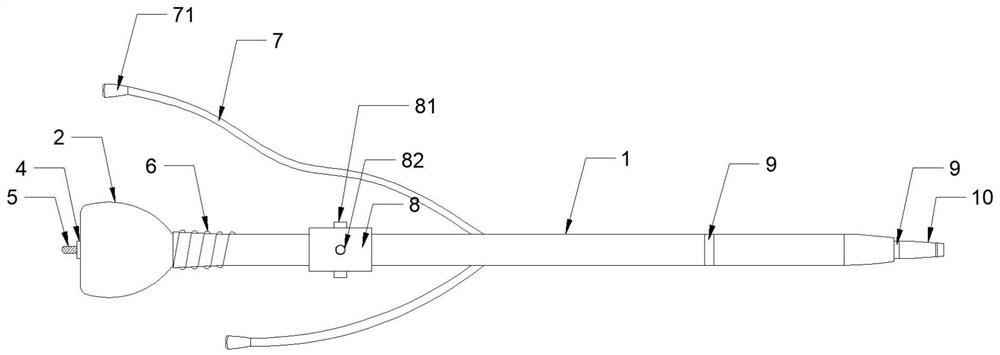
[0035] Such as Figure 3-5 As shown, the difference between this embodiment and Embodiment 1 is that: the side of the tube body 1 is connected with a plurality of branch pipes 7, and the top ends of the branch pipes 7 are respectively provided with corresponding liquid injection ports 71, from which the liquid injection ports 71 can be inwardly Adding medicine to the tube 3 can reduce the surgical wound, reduce the user's physical pain, and can speed up the surgical process without direct contact with the guide wire 5, and the rest are the same as in the first embodiment.

Embodiment 3

[0037] Such as Figure 1-5 As shown, the difference between this embodiment and Embodiment 2 is that the connection mode between the ferrule 8 and the outer circumference of the pipe body 1 is set as a sliding connection, the ferrule 8 is detachable, and the surface of the ferrule 8 and the connecting piece 82 are all provided with There is a through hole corresponding to the rotating shaft 84, and the surface of the rotating shaft 84 and the wall surface of the through hole are provided with corresponding threads. Using the rotating shaft 84 to fix the pipe body 1 can effectively prevent the pipe body 1 from shaking, and the rest are the same as in embodiment 2.

[0038] During the implementation process, the catheter tip 10 is pushed into the blood vessel from the coronary artery puncture, and pushed backward along the blood, and the guide wire 5 in the lumen 4 is pushed into the blood vessel accordingly. There are 6 windings of elastic wire, which can effectively prevent th...


PUM


Abstract

The invention relates to the technical field of medical instruments, in particular to a micro catheter assembly which comprises a catheter body. A catheter base is arranged at the top end of the catheter body, an inner catheter and a cavity catheter arranged on the periphery of the inner catheter are arranged in the catheter body, a solution cavity located outside the cavity catheter is formed in the catheter base, a guide wire is arranged in the cavity catheter, and a clamping sleeve is installed on the periphery of the catheter body. A catheter tip is arranged at the tail end of the catheter body, and a water-soluble degradable coating is arranged on the surface of the catheter tip. By arranging the clamping sleeve in sliding connection with the periphery of the catheter body, the use safety of the micro catheter is improved by rotating the advancing direction of the catheter body; stress mutation of the micro catheter is effectively avoided through the elastic wire winding, and bending or deformation of the micro catheter in the propelling process is effectively avoided. The rotating shaft is prevented from excessively pressing the catheter body through the connecting piece provided with the spring, and circulation of the guide wire and liquid medicine in the catheter body is achieved; by arranging a plurality of branch pipes used for adding medicine, operation wounds are reduced, the physiological pain of a user is reduced, and the operation process is accelerated.

Description

technical field [0001] The invention relates to the technical field of medical instruments, in particular to a microcatheter assembly. Background technique [0002] Medical microcatheter components are generally divided into radiography and microparticle injection, which are mainly used to enhance the support force of the guide wire in coronary artery surgery, simplify complex lesion operations, and can also be applied to selective radiography. However, the existing microcatheter assembly is usually a single-lumen catheter, and the drug solution is often in direct contact with the guide wire, and its drug effect is easily affected. Moreover, the microcatheter after being pushed into the blood vessel has poor flexibility and is easily deformed or bent. [0003] The patent with the publication number CN103635222B discloses a microcatheter with a distal tip part and a proximal solution lumen, and proposes a "slender tubular body with a proximal end of the main body, a distal en...

Claims


Application Information

Patent Timeline
Patent Type & Authority Applications(China)
IPC IPC(8): A61M25/00A61M5/00
CPCA61M25/00A61M5/007A61M2025/0063A61M25/0068
Inventor 黄奉康邓一兰杨安顺
Owner 四川艾迈思生物医疗科技股份有限公司
Why Eureka
Try Eureka