A grinding structure design method for vertical mills with different grinding zones

A technology of structural design and grinding area, which is applied in the field of vertical mill grinding structure design, can solve the problems of low grinding efficiency, short residence time, insufficient grinding, etc., and achieve the effect of improving grinding efficiency, reducing cycle load and fully grinding

Active Publication Date: 2022-05-17
TIANJIN CEMENT IND DESIGN & RES INST
View PDF6 Cites 1 Cited by
  • Summary
  • Abstract
  • Description
  • Claims
  • Application Information

AI Technical Summary

Problems solved by technology

The existing grinding zone structure has the following defects when grinding materials: (1) The residence time of the material in the grinding zone is too short, and it crosses the edge of the grinding disc without being fully ground, and the grinding is insufficient; (2) The material to be ground is divided into powder Machine return material and new feed material, the new feed particles are relatively coarse, the powder classifier return material is relatively fine, the coarse and fine particles are ground under the same grinding action, and the grinding efficiency is low

Method used


Image

  • A grinding structure design method for vertical mills with different grinding zones
  • A grinding structure design method for vertical mills with different grinding zones
  • A grinding structure design method for vertical mills with different grinding zones

Examples


Embodiment Construction

[0040] In order to make the object, technical solution and advantages of the present invention more clear, the present invention will be further described in detail below in conjunction with the examples. It should be understood that the specific embodiments described here are only used to explain the present invention, not to limit the present invention.

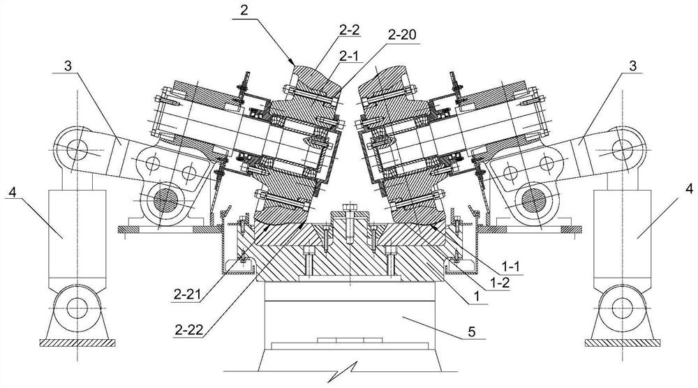
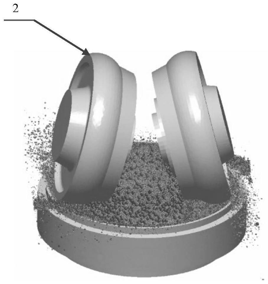
[0041] see figure 1 and figure 2 A method for designing the grinding structure of a vertical mill with different grinding zones, characterized in that the grinding structure of the vertical mill includes a grinding disc 1 and a grinding roller 2, and the above-mentioned grinding roller is designed as a composite roller, and the specific structure is as follows: the grinding roller includes a grinding roller The main body 2-1, the roller sleeve 2-2 is set on the grinding roller body, and connected by fasteners to form a cone composite roller; the roller sleeve is provided with a central hole 2 that fits the outer surface o...


PUM


Abstract

The invention discloses a method for designing the grinding structure of a vertical mill with different grinding areas. The grinding structure of the vertical mill includes a grinding disc and a grinding roller. The above-mentioned grinding roller is designed as a composite roller. The specific structure is as follows: The roller body is covered with a roller sleeve to form a cone composite roller; the outer surface of the roller sleeve includes a protruding curved tire roller section and a tapered roller section from the large diameter end to the small diameter end, and the curvature radius of the grinding table is consistent with that of the grinding roller. The groove is equipped with a wear-resistant liner on the inner edge of the groove toward the center of the grinding disc; the end of the wear-resistant liner near the side of the retaining ring is provided with a curved surface whose curvature radius is consistent with that of the grinding roller; the tapered roller section of the above-mentioned grinding roller and Grinding zone I and grinding zone II are formed between the wear-resistant liner and the grinding disc, and then the main parameters and calculations of the grinding structure are established. The above scheme improves the grinding efficiency and reduces the cycle load; it increases the difficulty for the material to leave the grinding disc, prolongs the time for the material to stay on the grinding disc, and makes the material grind more fully; The particles have a targeted crushing effect, and can exert excellent effects in the classification and grinding technology.

Description

technical field [0001] The invention belongs to the technical field of grinding, and in particular relates to a grinding structure design method of a vertical mill with different grinding zones. Background technique [0002] Vertical roller mill, referred to as vertical mill, is a mill used to grind raw materials such as cement raw meal, cement clinker, slag, cinder, etc. It is mainly composed of a machine body, a transmission device, a grinding disc, and a grinding roller. When working, the motor drives the grinding disc to rotate through the reducer, and the material falls to the center of the grinding disc from the inlet through the air lock feeder, and the hot air enters the mill from the air inlet at the same time. As the grinding table rotates, the material moves to the edge of the grinding table under the action of centrifugal force. When passing through the grinding area at the bottom of the grinding roller, it is sheared and crushed by the grinding roller. The crush...

Claims


Application Information

Patent Timeline
Patent Type & Authority Patents(China)
IPC IPC(8): B02C15/00
CPCB02C15/007B02C15/004B02C15/003Y02P40/10
Inventor 豆海建何小龙唐清华刘畅秦景平于涛
Owner TIANJIN CEMENT IND DESIGN & RES INST
Why Eureka
Try Eureka