
Solar photovoltaic panel surface cleaning system and cleaning method

A photovoltaic panel surface and cleaning system technology, applied in cleaning methods and appliances, cleaning methods using gas flow, photovoltaic power generation, etc., can solve the problems of time-consuming and labor-intensive manual cleaning, low cleaning efficiency, and high labor costs, and achieve Cleaning efficiency is efficient and fast, reducing cleaning costs and reducing load weight

Active Publication Date: 2021-10-01
XIAN THERMAL POWER RES INST CO LTD
View PDF8 Cites 1 Cited by
  • Summary
  • Abstract
  • Description
  • Claims
  • Application Information

AI Technical Summary

Problems solved by technology

[0005] The purpose of the present invention is to overcome the shortcomings of the above-mentioned prior art, and provide a method and system for cleaning the surface of solar photovoltaic panels to solve the problem of manual cleaning in the prior art. Time-consuming and labor-intensive, high labor costs, low cleaning efficiency and high cost by dry ice blasting

Method used


Image

  • Solar photovoltaic panel surface cleaning system and cleaning method
  • Solar photovoltaic panel surface cleaning system and cleaning method
  • Solar photovoltaic panel surface cleaning system and cleaning method

Examples


Embodiment 1

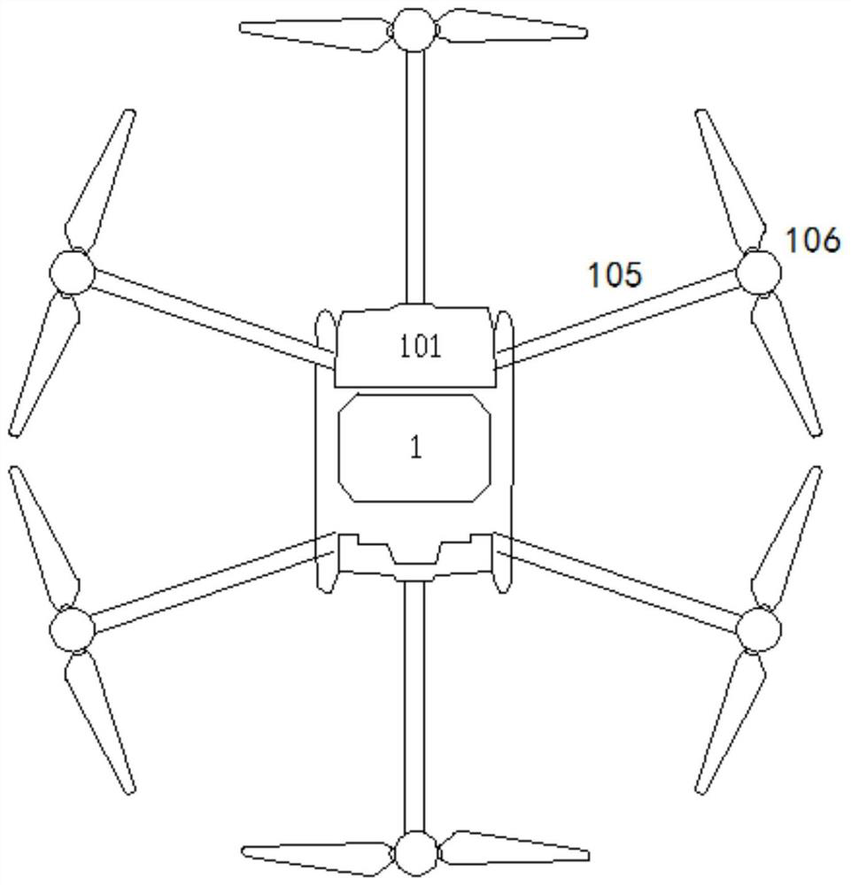
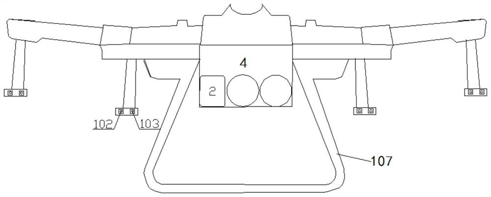
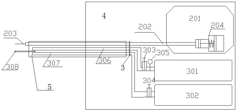
[0058] The drone inspects the photovoltaic panels, determines the specific location information of the stains on the photovoltaic panels through the infrared camera 102 and the stain positioning system 101, and then controls the drone to hover within 1 meter near the spot of the stains, and aligns the nozzle 203 with the stains on the photovoltaic panels , adjust the diaphragm pump 204 flow rate to 2L / min, the working time is 5 seconds, start the diaphragm pump 204, so that the cleaning liquid is sprayed from the nozzle 203; after the diaphragm pump 204 stops working for 5 seconds, first open the solenoid valve 303 to adjust the carbon fiber nitrogen cylinder The outlet pressure of the decompression valve 305 of 301 is 0.3MPa, so that nitrogen is ejected from the nozzle 308 to clean the impurity gas in the pipeline; after 2 seconds, the second solenoid valve 304 is opened to output liquid carbon dioxide; carbon dioxide is formed at the nozzle 308 snow, and spray carbon dioxide ...

Embodiment 2

[0060] The drone inspects the photovoltaic panels, determines the specific location information of the stains on the photovoltaic panels through the infrared camera 102 and the stain positioning system 101, and then controls the drone to hover within 1 meter near the spot of the stains, and aligns the nozzle 203 with the stains on the photovoltaic panels , adjust the diaphragm pump 204 flow rate to 3L / min, the working time is 5 seconds, start the diaphragm pump 204, so that the cleaning liquid is sprayed from the nozzle 203; after the diaphragm pump 204 stops working for 5 seconds, first open the solenoid valve 303 to adjust the carbon fiber nitrogen cylinder The outlet pressure of the pressure reducing valve 305 of 301 is 0.4MPa so that nitrogen is ejected from the nozzle 308 to clean the impurity gas in the pipeline; after 2 seconds, the solenoid valve 304 is opened to output the liquid carbon dioxide; carbon dioxide snow is formed at the nozzle 308, and Spray carbon dioxide ...


PUM


Abstract

The invention provides a solar photovoltaic panel surface cleaning system and a cleaning method. The system is characterized in that the whole cleaning device is arranged on an unmanned aerial vehicle, an infrared camera and a visible light camera which are used for shooting are arranged on the unmanned aerial vehicle, a stain positioning system used for positioning is further arranged on the unmanned aerial vehicle, and meanwhile, a device for loading cleaning liquid and a device for loading carbon dioxide are arranged. Compared with an existing photovoltaic panel decontamination technology, the system adopts an environment-friendly stain cleaning agent, the surface of a solar photovoltaic panel is sprayed with the stain cleaning agent, meanwhile, a carbon dioxide snow decontamination technology is matched, so that residual stains are cleaned again without leaving water stains; and therefore, the problem of water shortage in regions such as deserts or gobi is solved.

Description

technical field [0001] The invention belongs to the technical field of solar photovoltaic panel power generation, and relates to a method and system for cleaning the surface of a solar photovoltaic panel. Background technique [0002] With the advancement of technology in recent years, photovoltaic power generation has been widely used and developed rapidly due to its environmental protection and renewable advantages, and the cost per unit energy of existing solar power generation has dropped significantly to the level of thermal power generation. Because large-scale solar photovoltaic power stations are often distributed in sparsely populated areas such as open deserts and Gobi, solar photovoltaic panels are placed in exposed harsh environments for a long time, and their surfaces will be polluted by sandstorms, ice and snow, and bird droppings. The heat conversion rate is greatly reduced, and because the polluted part cannot work normally, the temperature is too high and bu...

Claims


Application Information

Patent Timeline
IPC IPC(8): B08B7/00B08B5/02B08B13/00H02S40/10B64D47/08B64D47/00B64C27/08B64C39/02
CPCB08B7/0092B08B5/02B08B13/00H02S40/10B64D47/08B64D47/00B64C27/08B64C39/024B64U30/20B64U10/10B64U2101/00Y02E10/50
Inventor 郭中旭杨嵩姚明宇郑天帅程广文付康丽赵瀚辰蔡铭
Owner XIAN THERMAL POWER RES INST CO LTD
Learn More