Check patentability & draft patents in minutes with Patsnap Eureka AI!

Arc surface dust blocking tool and rotary target material thermal spraying device using the same

A dust-proof and curved surface technology, which is applied in coating, fusion spraying, metal material coating process, etc., can solve the problems of overheating at the end of the target, poor thermal conductivity, and reduced production efficiency, so as to reduce thermal stress, The effect of improving service life and improving product yield

Pending Publication Date: 2021-10-01
广州市尤特新材料有限公司
View PDF0 Cites 0 Cited by
  • Summary
  • Abstract
  • Description
  • Claims
  • Application Information

AI Technical Summary

Problems solved by technology

For the ceramic target, due to its poor thermal conductivity, the dust-proof tooling protective cover at both ends of the target is easy to accumulate heat and overheat the end of the target, which will lead to cracking of the target to a certain extent.
On the other hand, the specification and size of the protective cover of the dust-proof tooling should match the thickness of the coating; when the thickness of the coating changes, the entire dust-proof tooling needs to be disassembled and replaced, which increases costs and reduces production efficiency

Method used


Image

  • Arc surface dust blocking tool and rotary target material thermal spraying device using the same
  • Arc surface dust blocking tool and rotary target material thermal spraying device using the same
  • Arc surface dust blocking tool and rotary target material thermal spraying device using the same

Examples


Embodiment Construction

[0020] The present invention has been further described in detail below in conjunction with specific embodiments.

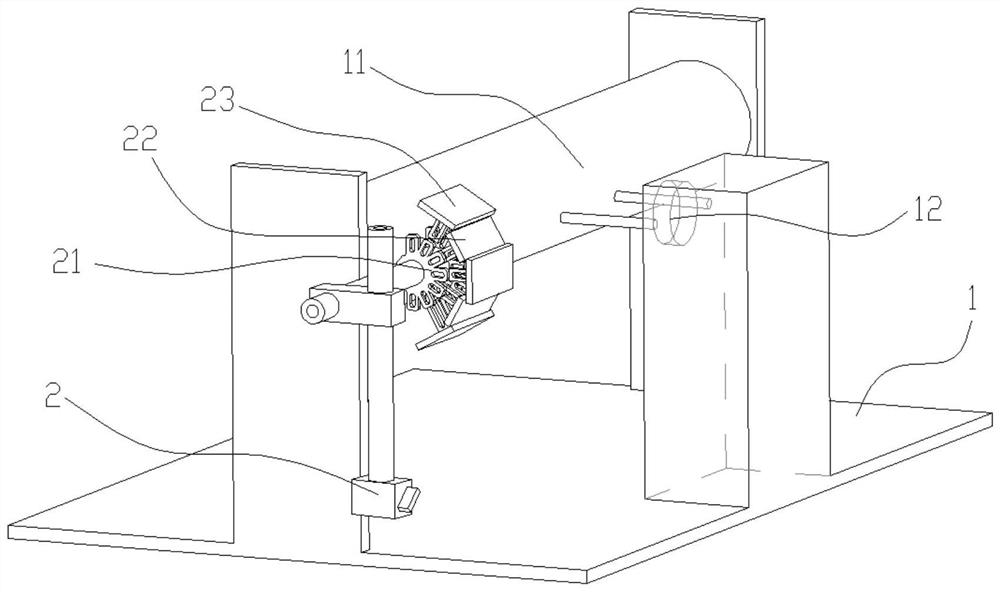
[0021] like figure 1 As shown, the rotating target thermal spray device 1 includes a target mounting position 11, provided in a spray gun (not shown) on the target mounting position side, and the air outlet 12 on the other side, further comprising a target mounting The arc surface of the exit portion 12 side ends 2, the inner surface of the curved shutter of the curved shutter 2 is positive on the target mounting position. The rotating target thermal spray device is used for processing ceramic targets.

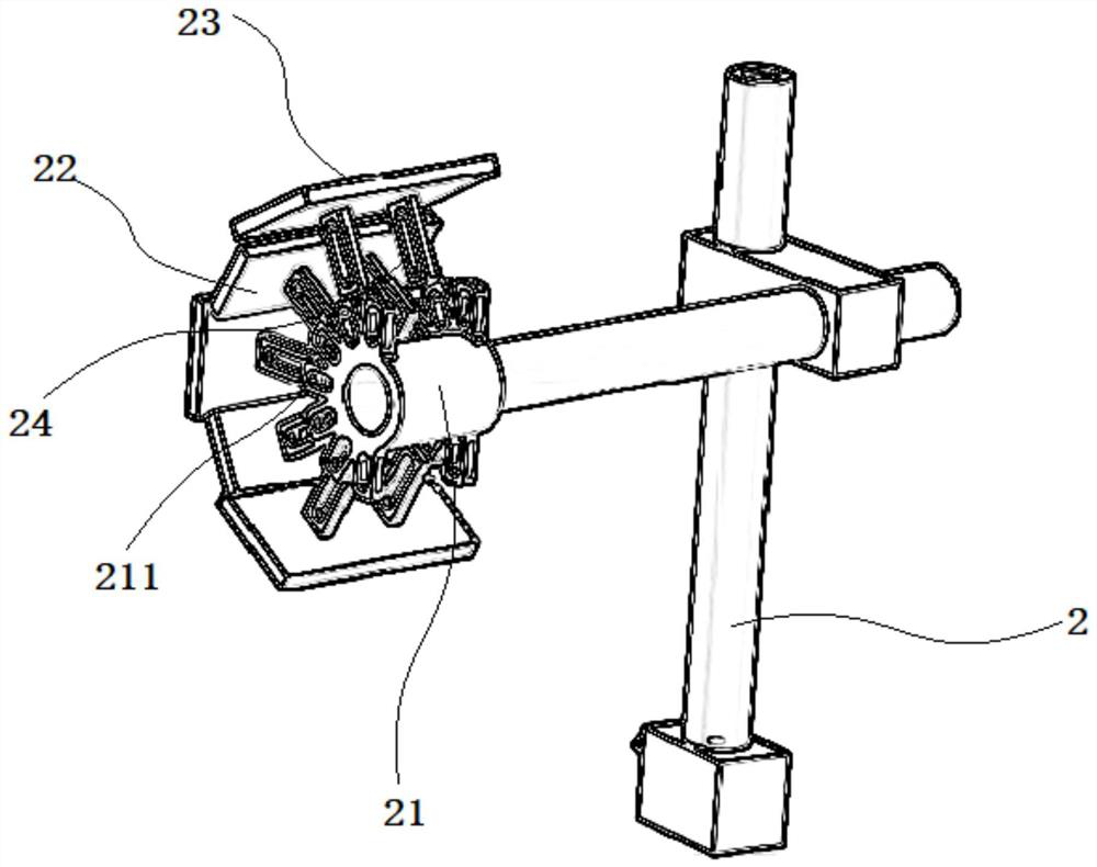
[0022] like figure 2 with image 3 As shown, the curved dust collecting 2 includes a support rod and a ring mount 21 and an arcuate baffle mounted on the end of the support rod. The support rod is laterally projecting the connecting rod, and the mounting seat 21 is sleeved in the end of the connecting rod around the center axis of the connecting rod. The mounting seat...


PUM


Abstract

The invention relates to the technical field of target material preparation, in particular to an arc surface dust blocking tool and a rotary target material thermal spraying device using the same. The rotary target material thermal spraying device using the arc surface dust blocking tool comprises a target material mounting position, an air outlet and an arc surface dust blocking tool, wherein the air outlet and the arc surface dust blocking tool are arranged on the same side, and the inner surface of an arc-shaped baffle of the arc-surface dust blocking tool right faces the target material mounting position. The arc surface dust blocking tool comprises a supporting rod, a mounting seat and arc-shaped baffles, wherein the mounting seat and the arc-shaped baffles are mounted at the tail end of the supporting rod, the inner surfaces of the baffles are connected with the mounting seat, the outer surfaces of the baffles are convex arc surfaces, a plurality of baffles are arranged, and the baffles are sequentially arranged around the mounting seat to form a dust blocking arc surface with the mounting seat as the center. The mounting seats and the baffles are mounted at the tail end of the supporting rod in a manner that the relative positions can be finely adjusted, so that the distances from the outer surfaces of the baffles to the supporting rod can be finely adjusted before dust is blocked; and when the arc surface dust blocking tool is used for spraying, the two ends of the target material are blocked to reduce dust, so that abnormities, such as cracking or poor compactness, of the end part of the target material are reduced, operation is simple, and mounting and adjusting are convenient.

Description

Technical field [0001] The present invention has created the field of preparation of the target, and in particular, to a curved shutter, a rotating target thermal spray apparatus for applying the dust collecting tool. Background technique [0002] The heat spray is to heat the coating material to the melt or semi-melt state by a variety of heat sources, and then atomize its atomization and high speed to the surface of the treated workpiece, which is often used in silicon target, silicon Preparation process of ceramic targets such as aluminum target and cerium oxide. [0003] Taking a rotating target as an example, the current thermal spray is in particular atmospheric spray, mostly used by the spray gun back and forth, and the workpiece is rotated at a certain speed to receive spraying, and there is a dust removal at the target end, and the thermal spray device is in the target. The sides are provided with extravasive air outlets that require dust from the side wall of the waste ...

Claims


Application Information

Patent Timeline
IPC IPC(8): C23C4/129
CPCC23C4/129
Inventor 吴健周志宏肖世洪周昭寅雷雨
Owner 广州市尤特新材料有限公司
Features
  • R&D
  • Intellectual Property
  • Life Sciences
  • Materials
  • Tech Scout
  • Unparalleled Data Quality
  • Higher Quality Content
  • 60% Fewer Hallucinations
Learn More