Vision-based mark-point-free bearing retainer contact angle measurement system and method

A technology of bearing cage and measurement method, which is applied in the field of contact angle measurement system of bearing cage without marking points, and can solve the problems of increasing the labor cost and complexity of the detection system, difficult measurement targets, and redundant equipment.

Active Publication Date: 2021-10-01
NORTH CHINA INST OF AEROSPACE ENG +2
View PDF8 Cites 1 Cited by
  • Summary
  • Abstract
  • Description
  • Claims
  • Application Information

AI Technical Summary

Problems solved by technology

However, similar to the disadvantages of fiber optic sensor speed measurement, machine vision speed measurement needs to be marked on the measurement target. Markers must be set for each bearing target to be measured, and the markers must be removed after the measurement. At the same time, the labor cost of the detection system and Complexity, and it may damage the bearing enamel, cause bearing surface corrosion, cause redundant equipment, and is not suitable for batch testing. It is difficult to use this method to measure targets for precision instruments

Method used


Image

  • Vision-based mark-point-free bearing retainer contact angle measurement system and method
  • Vision-based mark-point-free bearing retainer contact angle measurement system and method
  • Vision-based mark-point-free bearing retainer contact angle measurement system and method

Examples


Embodiment Construction

[0053] The following will clearly and completely describe the technical solutions in the embodiments of the present invention with reference to the accompanying drawings in the embodiments of the present invention. Obviously, the described embodiments are only some of the embodiments of the present invention, not all of them. Based on the embodiments of the present invention, all other embodiments obtained by persons of ordinary skill in the art without making creative efforts belong to the protection scope of the present invention.

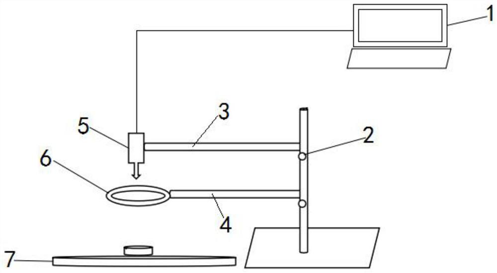
[0054] The purpose of the present invention is to provide a vision-based non-marking point bearing cage contact angle measurement system and method, with simple operation, high monitoring efficiency, strong portability and stability, and overcomes the general sensor detection method and the traditional one. The disadvantage of visual speed measurement of marking points is that the non-contact, high-precision real-time measurement of the bearing ca...


PUM


Abstract

The invention provides a vision-based mark-point-free bearing retainer contact angle measurement system and method, and the method comprises the steps: collecting a dynamic image of a bearing through an industrial camera, processing the image through an upper computer, finding out motion trails of all balls, employing the basic idea of combining an improved inter-frame difference algorithm with a feature matching square difference algorithm, subtracting the small angle that the circle of the image before each frame is rotated around the circle center from the gray value of the corresponding pixel point on the circle after the frame, calculating the quadratic sum of the difference, finding the minimum value, obtaining the rotating angle of the bearing retainer between frames, traversing all the collected images, obtaining the angles of all the images, obtaining the rotating speed information of the retainer through calculation, and calculating the contact angle. The vision-based mark-point-free bearing retainer contact angle measurement system and method provided by the invention are simple to operate and high in monitoring efficiency, realize non-contact and high-precision real-time measurement of the rotating speed of the bearing retainer under the condition that no marker is arranged, and reduce damage to a machine.

Description

technical field [0001] The invention relates to the technical field of bearing measurement, in particular to a vision-based system and method for measuring the contact angle of a bearing cage without marking points. Background technique [0002] Rolling bearings are composed of four parts: inner ring, outer ring, balls, and cage. The white ring in contact with the balls is the cage, which carries the balls. The contact angle refers to the angle between the line between the actual contact point between the inner and outer ring grooves and the steel ball and the radial plane parallel to the end face of the bearing when the ball bearing is subjected to axial load. The size of the contact angle of the ball bearing will directly affect the bearing capacity, rigidity and working reliability of the bearing. The value of the contact angle of the bearing should be controlled according to the requirements during the production process. The calculation of the contact angle requires th...

Claims


Application Information

Patent Timeline
Patent Type & Authority Applications(China)
IPC IPC(8): G01B11/26G01M13/04G06T7/12G06T7/66G06T7/73
CPCG01B11/26G01M13/04G06T7/12G06T7/66G06T7/73G06T2207/10016G06T2207/10024G06T2207/20024G06T2207/30108
Inventor 郝铎贾一阳吴浩文焦凯龙
Owner NORTH CHINA INST OF AEROSPACE ENG
Why Eureka
Try Eureka