Dual-frequency long-focal-depth ultrasonic transducer based on stack arrangement

An ultrasonic transducer and ultrasonic technology, applied in the fields of ultrasonic/photoacoustic microscopic imaging and non-destructive testing, can solve the problems that it is difficult to realize small focal spot, long focal depth and narrow bandwidth at the same time

Inactive Publication Date: 2021-10-08
NORTHWESTERN POLYTECHNICAL UNIV
View PDF11 Cites 1 Cited by
  • Summary
  • Abstract
  • Description
  • Claims
  • Application Information

AI Technical Summary

Problems solved by technology

[0006] The object of the present invention is to provide a dual-frequency long-focus ultrasonic transducer based on a stack arrangement to solve the problem that the existing focused ultrasonic detector has a narrow bandwidth and is difficult to realize a small focal spot and a long focal depth at the same time

Method used


Image

  • Dual-frequency long-focal-depth ultrasonic transducer based on stack arrangement
  • Dual-frequency long-focal-depth ultrasonic transducer based on stack arrangement
  • Dual-frequency long-focal-depth ultrasonic transducer based on stack arrangement

Examples


Embodiment 1

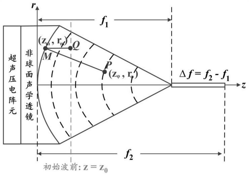
[0041] In Example 1, the aspherical acoustic matching layer scheme was adopted to realize the development of a dual-frequency long-focus ultrasonic transducer, figure 2 shown.

[0042] The method for preparing the curved surface structure of the aspheric acoustic matching layer in Example 1. figure 2 As shown, when the ultrasonic wave transmits through any point M(r on the long focal depth aspheric acoustic lens m ,z m ), use the formula in step 4 to find the point corresponding to the wavefront function after being focused by the acoustic lens (That is, there is a one-to-one correspondence between point P and point M). The equal sound path principle means that no matter how the point M is selected, there is always MQ+MP=K (constant). Because the acquisition of the acoustic wavefront function is to solve a differential equation, an arbitrary constant can be added to the obtained function result, corresponding to which the function can be translated along the abscissa z ax...

example 1

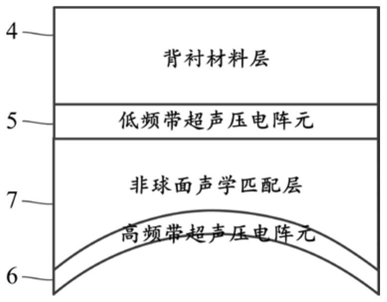
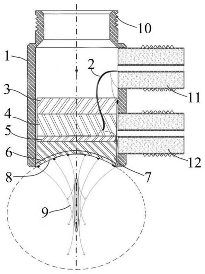
[0061] In Example 1, the acoustic focal length of the ultrasonic transducer is required to be 10MM, wherein the aspheric acoustic matching layer 7 is made of epoxy resin material, and the total length is 6MM. After the sound insulation layer 3, the backing material layer 4, and the low-frequency ultrasonic piezoelectric array element 5 are arranged in the inner cavity of the housing 1, the aspheric acoustic matching layer 7 is fixed on the low-frequency ultrasonic piezoelectric array element 5 with 301 epoxy optical glue The lower end of the housing is completely sealed.

[0062] A dual-frequency long-focus ultrasonic transducer based on a stack arrangement in Example 1 was used to test its sound field performance.


PUM


Abstract

The invention discloses a dual-frequency long-focal-depth ultrasonic transducer based on stack arrangement. The dual-frequency long-focal-depth ultrasonic transducer based on stack arrangement comprises a shell, a sound insulation layer, a backing material layer, low-frequency-band ultrasonic piezoelectric array elements, high-frequency-band ultrasonic piezoelectric array elements, a signal line and an aspheric acoustic matching layer; and the low-frequency-band ultrasonic piezoelectric array elements and the high-frequency-band ultrasonic piezoelectric array elements adopt a one-dimensional stack arrangement structure. The curved surface structure of the aspheric acoustic matching layer is reversely deduced by an equal sonic path distance principle and a wavefront function, and the aspheric acoustic matching layer is arranged between the low-frequency-band ultrasonic piezoelectric array elements and the high-frequency-band ultrasonic piezoelectric array elements. A scheme of combining one-dimensional stack arrangement of the dual layers of ultrasonic piezoelectric array elements and an aspheric focusing structure is adopted, so that acoustic characteristics of large depth of field and broadband ultrasonic excitation and reception can be obtained. The invention belongs to aspheric focusing long-focal-depth dual-frequency ultrasonic detectors, and belongs to the technical field of ultrasonic/photoacoustic imaging and nondestructive testing.

Description

technical field [0001] The invention belongs to the technical fields of ultrasonic / photoacoustic microscopic imaging and non-destructive testing, and relates to a dual-frequency long-focus ultrasonic transducer based on a stack arrangement, and also relates to the acoustic detection and focusing technology of the ultrasonic transducer. Background technique [0002] Photoacoustic microscopy is a high-resolution photoacoustic imaging method developed on the basis of photoacoustic imaging. According to different focusing modes, photoacoustic microscopy can be further divided into optical resolution photoacoustic microscopy and acoustic resolution photoacoustic microscopy. Photoacoustic microscopy with optical resolution mainly relies on quasi-ballistic photons to provide optically defined lateral resolution, and its penetration depth is still limited to ~1.5 mm, which is difficult to meet the non-destructive high-resolution imaging requirements of superficial and deep human tis...

Claims


Application Information

Patent Timeline
Patent Type & Authority Applications(China)
IPC IPC(8): B06B1/06
CPCB06B1/0614
Inventor 马海钢黄庆华李学龙
Owner NORTHWESTERN POLYTECHNICAL UNIV
Why Eureka
Try Eureka