Speed-adjustable full-automatic servo line
A fully automatic, high-speed technology, applied in vibration suppression adjustment, forming tools, and ejection equipment, etc., can solve problems such as lower product qualification rate, difficulty in taking out, and deformation of raw materials, and achieve the effect of improving stamping accuracy and shock absorption
- Summary
- Abstract
- Description
- Claims
- Application Information
AI Technical Summary
Problems solved by technology
Method used
Image

Examples
Embodiment 1
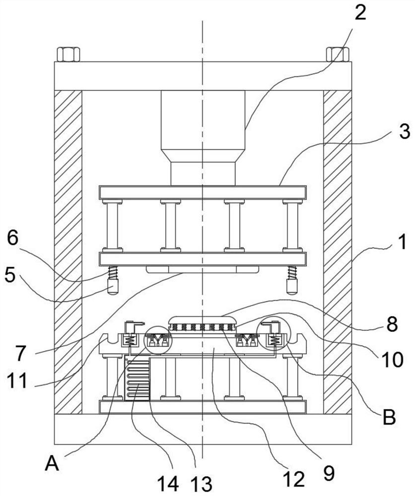
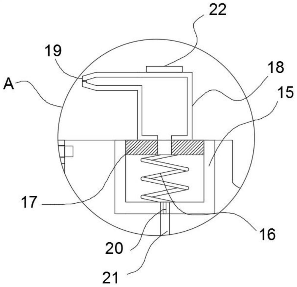
[0034] Refer to attached Figure 1-Figure 4 , a fully automatic servo line with adjustable speed in this embodiment, including a servo line body one 1 and a servo line body two 34, a water tank 13 is installed on the inner wall of the bottom of the servo line body one 1, and the inner wall of the water tank 13 is fixedly connected to a condenser 14, An insulation tank 15 is provided on the top of the workbench 12, and the inner wall of the insulation tank 15 is sleeved with a press-out cylinder 18, and a rubber plug 17 is installed at the bottom of the press-out cylinder 18, and a powerful spring 16 is installed at the bottom of the rubber plug 17, and a one-way valve is installed on the inner wall of the insulation tank 15. The valve 20 is fixedly connected to the high-pressure spray head 19 on one side of the press outlet cylinder 18, the bottom of the one-way valve 20 is fixedly connected to the outlet pipe 21, the top of the workbench 12 is provided with a lifting trough 23...
Embodiment 2
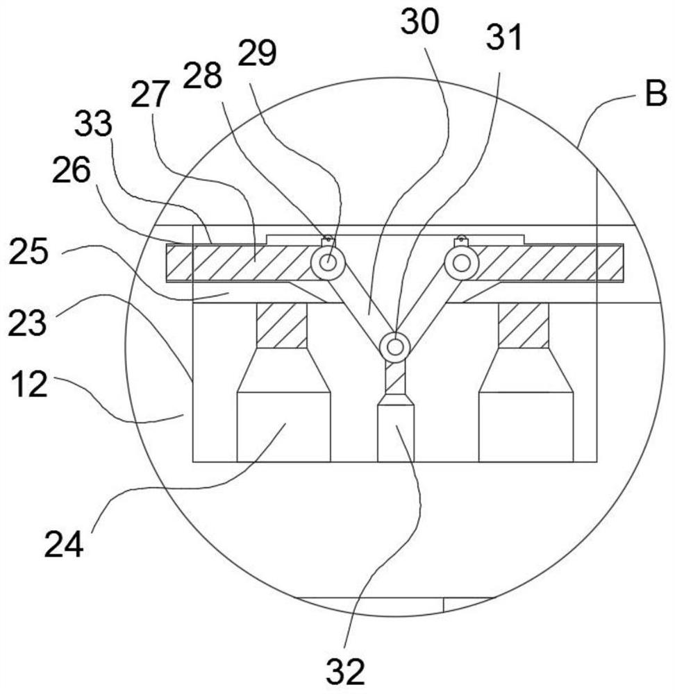
[0045] Refer to attached Figure 5-Figure 6 , a fully automatic servo line with adjustable speed in this embodiment, including a servo line body two 34, a reduction motor 35, an externally threaded rod 36 and an internally threaded tube 37, specifically, the servo line body two 34 includes a rotating shaft two 31 , the bottom end of rotating shaft two 31 is equipped with an internally threaded pipe 37, the outer surface of the internally threaded pipe 37 is sleeved with an externally threaded rod 36, and the bottom end of the externally threaded rod 36 is fixedly connected to the output end of the reduction motor 35, and the reduction motor 35 is installed in the lifting chute 23 The inner wall of the bottom drives the externally threaded rod 36 to rotate in the internally threaded tube 37 through the reduction motor 35, and the internally threaded tube 37 moves downward, driving the push-pull arm 30 to move down, and pulls the clamping plate 27 to exit the draw-in groove 26 th...
PUM
 Abstract
Description
Claims
Application Information
 - R&D Engineer
- R&D Manager
- IP Professional
- Industry Leading Data Capabilities
- Powerful AI technology
- Patent DNA Extraction
Browse by: Latest US Patents, China's latest patents, Technical Efficacy Thesaurus, Application Domain, Technology Topic.
© 2024 PatSnap. All rights reserved.Legal|Privacy policy|Modern Slavery Act Transparency Statement|Sitemap