Environment-friendly combustion equipment for environment-friendly power plant

A combustion equipment and power plant technology, applied in lighting and heating equipment, dispersed particle filtration, dispersed particle separation, etc., can solve problems such as polluting the environment, poisoning the health of operators, and ineffective gas treatment, so as to ensure timely The effect of cleaning, guaranteeing cleaning, and good adsorption effect

Inactive Publication Date: 2021-10-08
邓香
View PDF0 Cites 0 Cited by
  • Summary
  • Abstract
  • Description
  • Claims
  • Application Information

AI Technical Summary

Problems solved by technology

[0005] Aiming at the deficiencies of the prior art, the present invention provides an environmentally friendly combustion equipment for an environmentally friendly power plant, which has the advantages of ensuring the cleaning of polluted gases and the timely cleaning of the outer barrel and inner barrel, and solves most of the combustion problems. The gas produced by the equipment cannot be effectively treated, which will lead to the pollution of the environment and the health of the operators.

Method used


Image

  • Environment-friendly combustion equipment for environment-friendly power plant
  • Environment-friendly combustion equipment for environment-friendly power plant
  • Environment-friendly combustion equipment for environment-friendly power plant

Examples


Embodiment 1

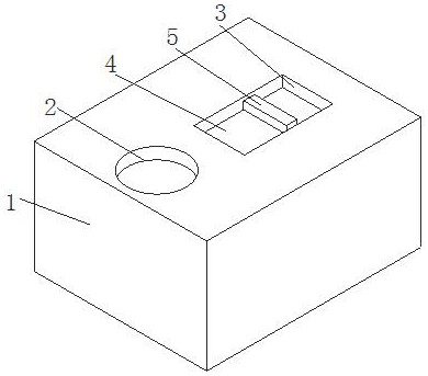
[0035] see Figure 1-Figure 3 , the present invention provides a new technical solution: an environmentally friendly combustion equipment for an environmentally friendly power plant, including a cleaning box 1, an inlet 2 is provided on the upper side of the cleaning box 1, and a chute 3 is provided on the upper side of the cleaning box 1 , the inside of the chute 3 is slidably connected with a slide plate 4, and the surface of the slide plate 4 is fixedly connected with a pull plate 5, and by pulling the pull plate 5, the slide plate 4 slides left and right in the inside of the chute 3, and because the slide plate 4 The inside of the chute 3 can only slide left and right without exposing the chute 3, thereby ensuring the sealing of the inside of the cleaning box 1. The lower surface of the pull plate 5 is fixedly connected with a connecting rod 6, and the lower end of the connecting rod 6 is fixedly connected with a moving plate 7. There is a water tank 8 inside the cleaning ...

Embodiment 2

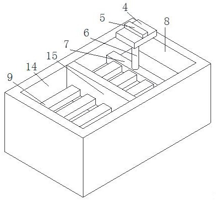
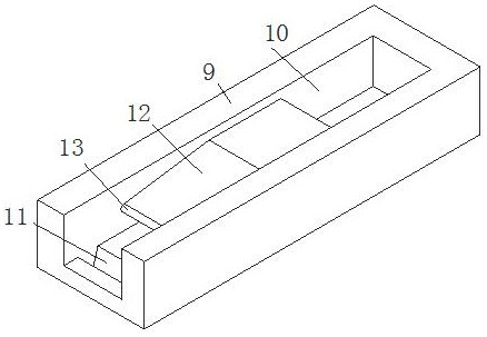
[0037] see Figure 4-Figure 5 , on the basis of Embodiment 1, the inside of the cleaning tank 1 is provided with a cleaning tank 14, and the junction of the water tank 8 and the cleaning tank 14 is fixedly connected with a partition plate 15, and the surface of the partition plate 15 is provided with a through groove 23, and the water outlet The surface of the plate 9 is slidably connected in the inside of the through groove 23, and the inside of the dividing plate 15 is provided with a lifting groove 16, and the inside of the lifting groove 16 is fixedly connected with a spring 24, and the lower end of the spring 24 is fixedly connected with a clamping plate 17, and the clamping plate 17 The surface of the surface is slidingly connected inside the lifting groove 16, and the sliding plate 4 slides left and right inside the sliding groove 3, so that the water outlet plate 9 slides to the left inside the through groove 23, and then the lower side of the clamping plate 17 is separat...

Embodiment 3

[0039] see Figure 6 , on the basis of Embodiment 1 and Embodiment 2, the inside of cleaning tank 14 is fixedly connected with outer barrel 18, the inside of outer barrel 18 is fixedly connected with connecting plate 19, and the surface of connecting plate 19 is fixedly connected with inner barrel 20, outer barrel 18 and the shape of inner barrel 20 are round table shape, and the surface of inner barrel 20 is fixedly connected with cleaning column 21, and the shape of cleaning column 21 is curved shape, and the lower end of inner barrel 20 is fixedly connected with suction fan 22, and suction fan 22 is existing structure, Without going into too much detail here, through the shape design of the outer barrel 18 and the inner barrel 20, under the action of the suction fan 22, the combustion gas is squeezed and filtered inside the outer barrel 18 and the inner barrel 20, and then the column 21 is cleaned. The curved barrier acts as a secondary filter. When it is necessary to clean...


PUM


Abstract

The invention relates to the technical field of combustion equipment, and discloses environment-friendly combustion equipment for an environment-friendly power plant. The environment-friendly combustion equipment comprises a cleaning box, an inlet is formed in the upper side of the cleaning box, a sliding groove is formed in the upper side of the cleaning box, a sliding plate is slidably connected into the sliding groove, a pulling plate is fixedly connected to the surface of the sliding plate, and the lower surface of the pulling plate is fixedly connected with a connecting rod. According to the environment-friendly combustion equipment for the environment-friendly power plant, through the shape design of an outer barrel and an inner barrel, under the air draft effect of a suction fan, combustion gas is extruded and filtered in the outer barrel and the inner barrel, and in this way, through the curve shape of a cleaning column, long-time contact is achieved during gas absorption, so that a good adsorption effect is achieved during the contact of the gas and the cleaning column; and the interior of the outer barrel and the interior of the inner barrel are cleaned through water flow, so that cleaning of the pollution gas is guaranteed, and timely cleaning of the interior of the outer barrel and the interior of the inner barrel is also guaranteed.

Description

technical field [0001] The invention relates to the technical field of combustion equipment, in particular to an environment-friendly combustion equipment for an environment-friendly power plant. Background technique [0002] Combustion equipment refers to collecting all kinds of garbage, classifying them, and then incinerating those with high combustion value at high temperature to convert the heat energy generated in high-temperature incineration into high-temperature steam. [0003] In the process of using most of the existing combustion equipment, although it can achieve a good incineration effect, a large amount of toxic and polluting gases will be produced during the combustion process, which will cause most of the existing combustion equipment to produce The gas cannot be treated effectively, which will lead to problems such as polluting the environment and poisoning the health of operators. Contents of the invention [0004] (1) Solved technical problems [0005]...

Claims


Application Information

Patent Timeline
Patent Type & Authority Applications(China)
IPC IPC(8): F23J15/02B01D46/00
CPCF23J15/02
Inventor 邓香
Owner 邓香
Why Eureka
Try Eureka