Full-automatic hot blast stove

A hot blast stove, fully automatic technology, used in air heaters, fluid heaters, lighting and heating equipment, etc., can solve the problems of cumbersome operation, high temperature, insufficient precision, etc., to ensure smooth operation, increase heat dissipation area, improve The effect of thermal efficiency

Pending Publication Date: 2021-10-08
YANCHENG INST OF TECH
View PDF5 Cites 0 Cited by
  • Summary
  • Abstract
  • Description
  • Claims
  • Application Information

AI Technical Summary

Problems solved by technology

[0003] At present, the fuel hot blast stove is mainly composed of a combustion chamber, a heat exchanger and a blower. The heat exchanger is placed above the combustion chamber. The advancement of the feed chain rail grate is determined by manual observation from the burner port and judging the combustion situation based on experience, or The time relay is used to control the push material, its precision is not enough, and it requires high judgment of people
The patent number is 03213919.5 invention patent, which discloses a fuel hot blast stove. The heat exchanger used is a reciprocating cycle structure with heat exchange tubes arranged horizontally and layered. The exhaust speed of the smoke is relatively slow, and more smoke can be used It can realize automatic control through single-chip microcomputer and temperature sensor; it has dust removal and slag discharge device; although it solves the problem of manually controlling the operation of the feed chain rail grate, the circulating fan sucks cold air to support the fuel in the furnace, and the cold air passes through The circulating fan and heat exchanger are heated and discharged from the hot air outlet
In this way, the combustion of fuel in the combustion chamber will generate high temperature in the furnace body, which will easily damage the components in the furnace body.
Moreover, the heat exchange tubes arranged horizontally and in layers are prone to deposits of furnace ash, and a dust cleaning device is required, which has a complex structure and cumbersome operation

Method used


Image

  • Full-automatic hot blast stove
  • Full-automatic hot blast stove
  • Full-automatic hot blast stove

Examples


Embodiment 1

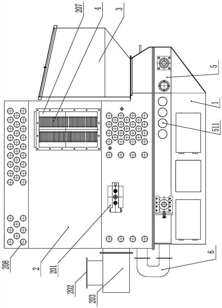
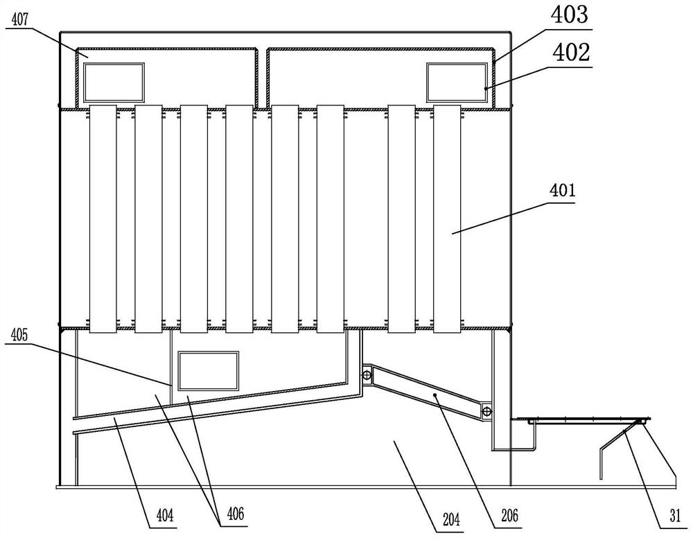
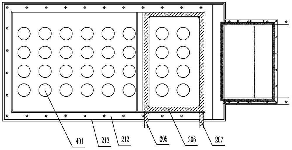
[0043] Embodiment 1: as figure 1 , figure 2 , Figure 6 Shown, the present invention comprises base 1, furnace body 2, material storage bin 3, fire grate seat 5, air blower, single-chip microcomputer, feeding device 8, temperature sensor 9 and combustion chamber 204, heat exchanger 4 in body of furnace 2, so The furnace body 2 is placed on the base 1 through the grate seat 5, the feeding device 8 is placed in the grate seat 5, the heat exchanger 4 is above the combustion chamber 204 in the furnace body 2, and the furnace body 2 is close to the storage bin 3 and corresponds to One side of the heat exchanger 4 has a hot air outlet 211, and the corresponding other side is connected with a blower, such as figure 2 , image 3As shown, the heat exchanger 4 communicates with the combustion chamber 204 and is separated by a first partition 404, including multiple sets of hot air pipes 401 arranged side by side vertically, a deflector 403 and a dust settling chamber 406. Above th...


PUM


Abstract

The invention relates to a full-automatic hot blast stove, and belongs to the technical field of hot blast stoves. The full-automatic hot blast stove comprises a stove body, a base, a fire grate seat, a storage bin, an air blower, a single chip microcomputer, a feeding device, a temperature sensor, a combustion chamber and a heat exchanger, the combustion chamber and the heat exchanger are arranged in the stove body, a hot blast outlet is formed in a stove shell, close to the storage bin and corresponding to one side of the heat exchanger, of the stove body, and the air blower is connected to the other corresponding side; the heat exchanger comprises multiple sets of hot blast pipes which are vertically arranged in parallel, a flow guide cover and a dust settling chamber, the flow guide cover with multiple circulating spaces is arranged above the multiple sets of hot blast pipes, and the dust settling chamber with multiple circulating areas is arranged below the multiple sets of hot blast pipes; and the hot blast pipes which are adjacently arranged in different circulating areas are combined into a same circulating space through the flow guide cover to form a smoke circulating channel, and the dust settling chamber at a circulating terminal is connected with a smoke outlet pipeline; and hot blast emitted from the hot blast pipes is blown out by the air blower. The heat exchanger achieves multi-return-stroke heat exchange and is high in heat efficiency, air inlet holes formed in the stove shell reduce the temperature of quick-wear parts, and the service life is long.

Description

technical field [0001] The invention belongs to the technical field of hot blast stoves, in particular to a fully automatic hot blast stove. [0002] technical background [0003] At present, the fuel hot blast stove is mainly composed of a combustion chamber, a heat exchanger and a blower. The heat exchanger is placed above the combustion chamber. The advancement of the feed chain rail grate is determined by manual observation from the burner port and judging the combustion situation based on experience, or The time relay is used to control the push material, but its precision is not enough, and it requires high judgment ability of people. The patent number is 03213919.5 invention patent, which discloses a fuel hot blast stove. The heat exchanger used is a reciprocating cycle structure with heat exchange tubes arranged horizontally and layered. The exhaust speed of the smoke is relatively slow, and more smoke can be used It can realize automatic control through single-chip ...

Claims


Application Information

Patent Timeline
Patent Type & Authority Applications(China)
IPC IPC(8): F24H3/08F24H9/00F24H9/02F24H9/18F23J1/00F23J15/02F23K3/00
CPCF24H3/088F24H9/0063F24H9/189F23J15/022F24H9/02F23J1/00F23K3/00F23K2203/103
Inventor 于玉真张王康荆孟杰
Owner YANCHENG INST OF TECH
Why Eureka
Try Eureka